

Implants with controlled drug delivery features and methods of using same
- Summary
- Abstract
- Description
- Claims
- Application Information
AI Technical Summary
Benefits of technology
Problems solved by technology
Method used
Image

Examples
Embodiment Construction
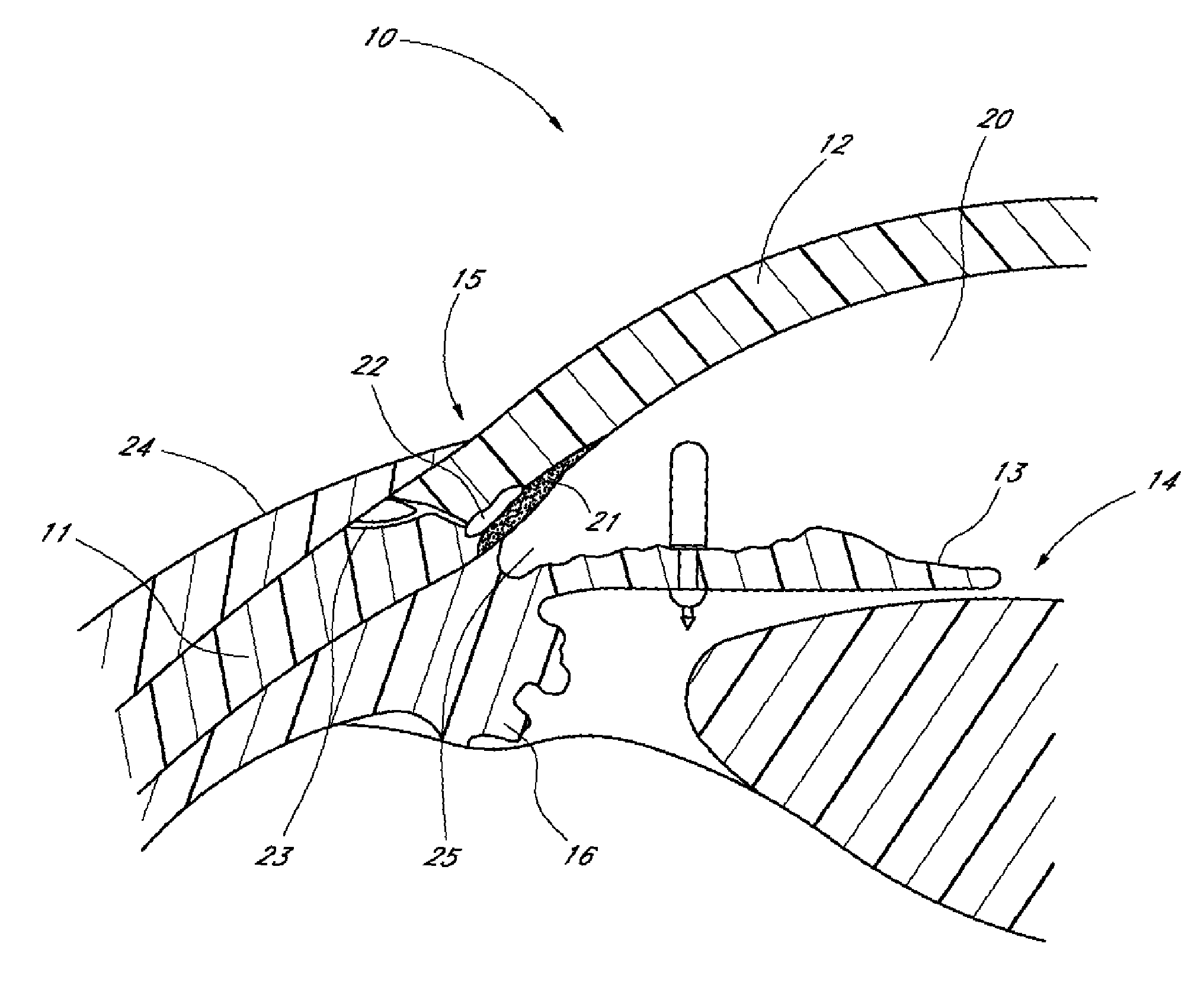
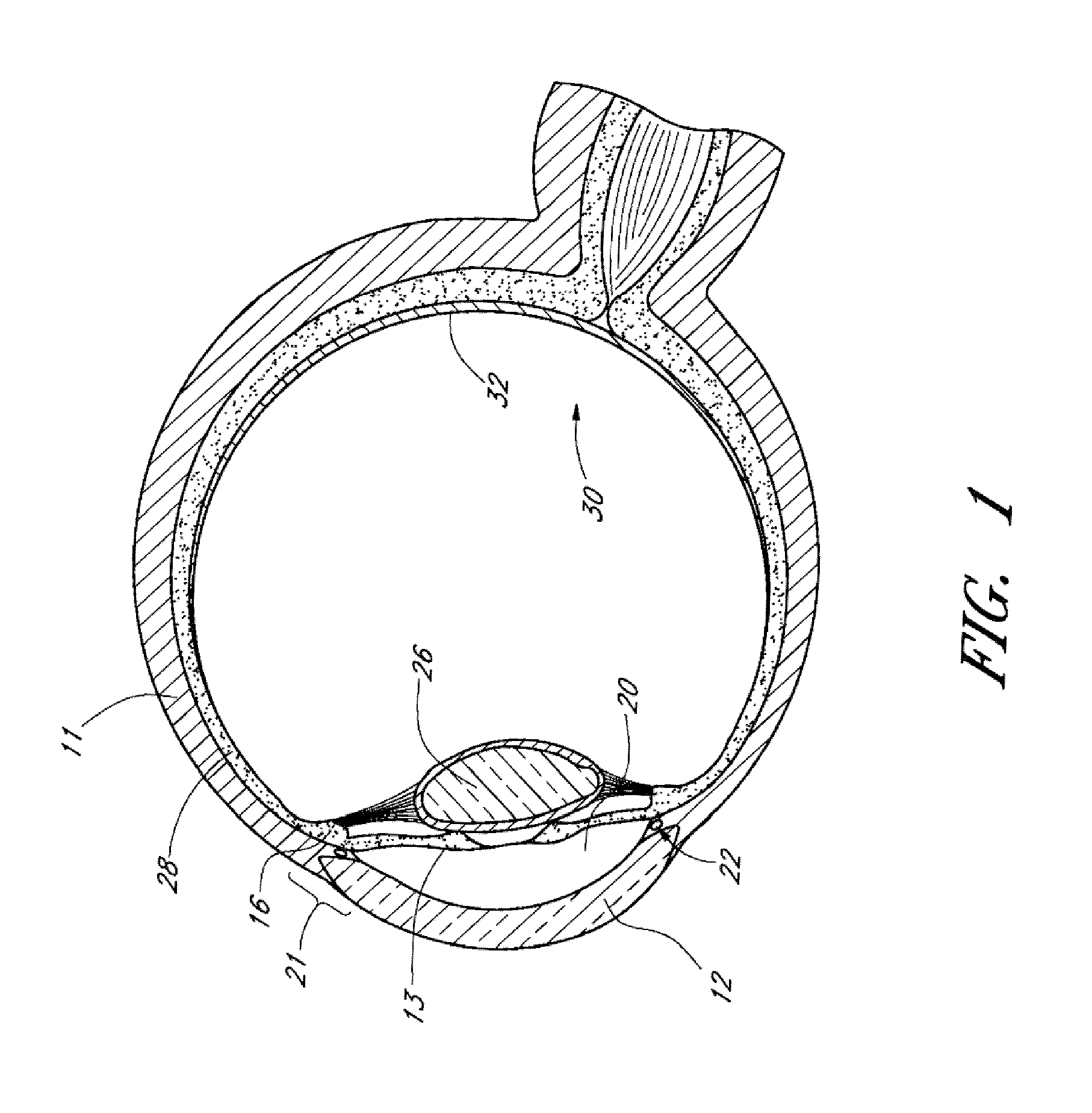
[0123]Achieving local ocular administration of a drug may require direct injection or application, but could also include the use of a drug eluting implant, a portion of which, could be positioned in close proximity to the target site of action within the eye or within the chamber of the eye where the target site is located (e.g., anterior chamber, posterior chamber, or both simultaneously). Use of a drug eluting implant could also allow the targeted delivery of a drug to a specific ocular tissue, such as, for example, the macula, the retina, the ciliary body, the optic nerve, or the vascular supply to certain regions of the eye. Use of a drug eluting implant could also provide the opportunity to administer a controlled amount of drug for a desired amount of time, depending on the pathology. For instance, some pathologies may require drugs to be released at a constant rate for just a few days, others may require drug release at a constant rate for up to several months, still others ...
PUM
 Abstract
Description
Claims
Application Information