

Intraocular physiological sensor
- Summary
- Abstract
- Description
- Claims
- Application Information
AI Technical Summary
Benefits of technology
Problems solved by technology
Method used
Image

Examples
Embodiment Construction
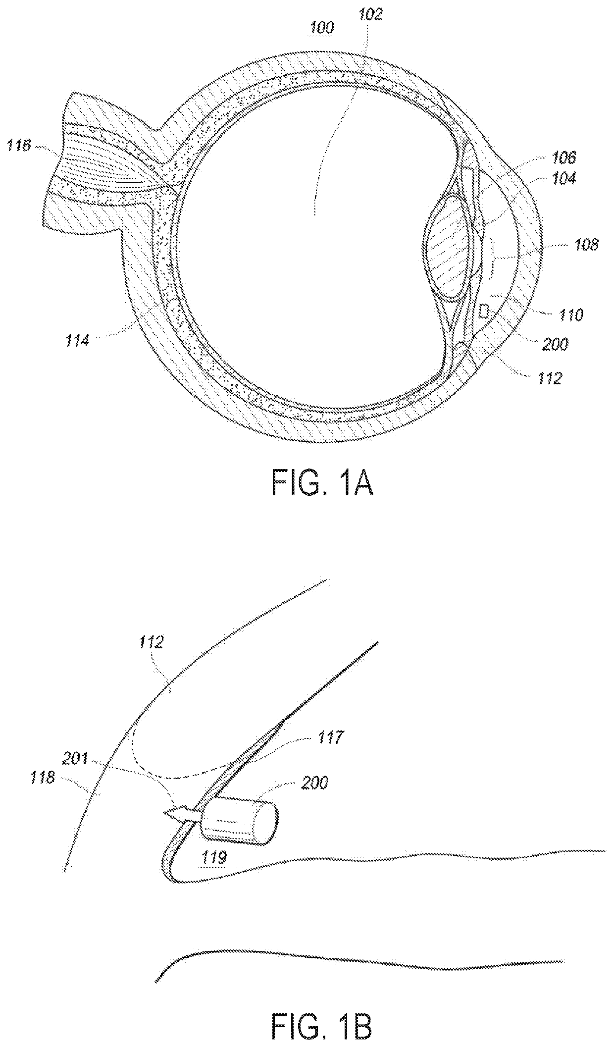
[0083]There is a need to effectively monitor intraocular pressure within a patient's eye in order to detect or monitor the progression of glaucoma. Intraocular pressure can be measured non-invasively using, for example, a tonometer. While tonometers have the advantage of being non-invasive, they have the disadvantages of generally being expensive, non-portable, specialized equipment that requires skilled operation. Accordingly, as a practical matter, it is difficult to use a tonometer to effectively monitor intraocular pressure in a patient's eye with a time resolution greater than one measurement every few days or weeks. However, since intraocular pressure can vary significantly over relatively short periods of time, such relatively sparse intraocular pressure measurements may not provide a complete or accurate picture of the patient's risk for, or progression of, glaucoma. It would therefore be advantageous to be able to measure intraocular pressure more often or even continuously...
PUM
 Abstract
Description
Claims
Application Information