Connector

a technology of connecting rods and shafts, applied in the direction of couplings/cases, coupling device connections, securing/insulating coupling contact members, etc., can solve the problem that the surface to be sealed by a surface seal or a shaft seal cannot ensure sufficient sealing performance, and the proper sealing state may not be maintained, etc. problems, to achieve the effect of inexpensive production

Active Publication Date: 2019-12-12
AUTONETWORKS TECH LTD +2
View PDF0 Cites 9 Cited by
  • Summary
  • Abstract
  • Description
  • Claims
  • Application Information

AI Technical Summary

Benefits of technology

[0011]According to the connector disclosed in this specification, inexpensive productio

Problems solved by technology

Thus, the flange may deform and a proper sealed state may not be maintained due to a resin creep phenomenon or the like.
Furthermore, a surface that is to be sealed by a surface seal or a shaft seal cannot

Method used


Image

  • Connector
  • Connector
  • Connector

Examples


Embodiment Construction

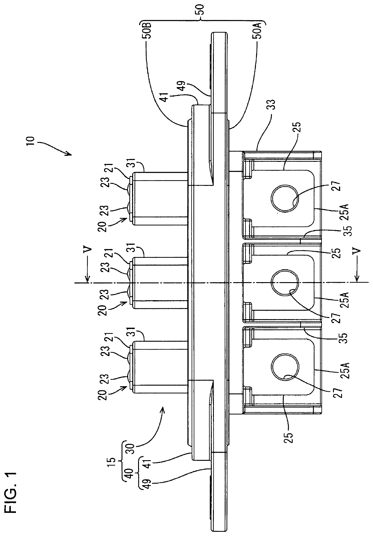
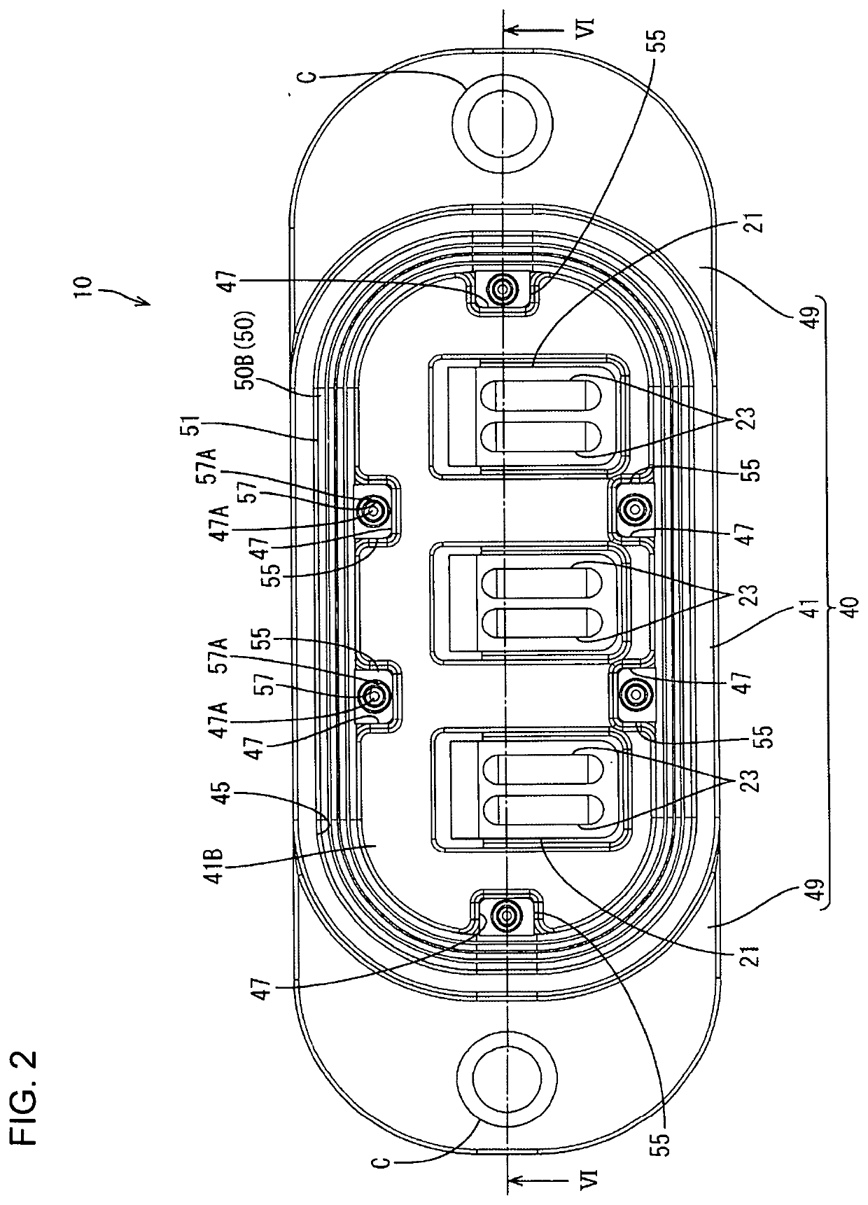
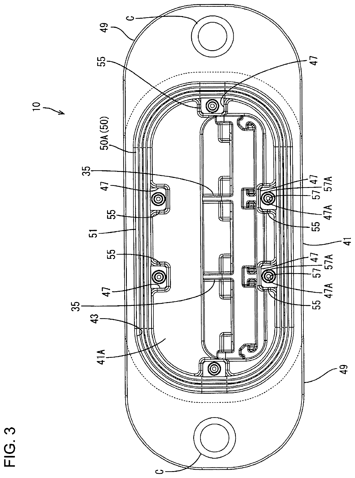
[0023]An embodiment is described with reference to FIGS. 1 to 11. A connector 10 of this embodiment is mounted on a case (motor-side case 60) of a motor (an example of a “first device”) as shown in FIG. 7. The connector 10 is overlapped on and fixed to an inverter PCU (an example of a “second device”; hereinafter, merely referred to as an inverter), thereby being connected to an inverter-side connector 80 (an example of a “mating connector”) mounted in an inverter-side case 90. The connector 10 includes terminals 20, a connector housing 15 with a terminal holding portion 30 and a flange 40, and sealing members 50 to be mounted the flange 40.

[0024]In the following description, a vertical direction is based on FIG. 8. Note that the vertical direction is an overlapping direction of the devices and, in this embodiment, an upper side is referred to as an inverter side and a lower side is referred to as a motor side. Further, a lateral direction is based on FIG. 8 and a left side in FIG. ...


PUM


Abstract

A connector (10) in a first device is connected to a mating connector (80) in a second device while overlapping and fixing the devices. The connector (10) includes a terminal holding portion (30) to hold terminals (20). A flange (40) on an outer periphery of the terminal holding portion (30) is sandwiched between cases (60, 90) of the devices. A first seal (50A) is mounted on a surface of the flange (40) facing the first device and seals between an outer surface of the case (60) of the first device and the flange (40), and a second seal (50B) is mounted on a surface of the flange (40) facing the second device and seals between an outer surface of the case (90) of the second device and the flange (40). Mounted positions of the seals (50A, 50B) are aligned in an overlapping direction of the first and second devices.

Description

BACKGROUNDField of the Invention[0001]This specification relates to a connector.Related Art[0002]Devices, such as a motor and an inverter, are connected to each other by connectors provided in cases of the respective devices. The cases are arranged to face each other and the connectors mounted in the cases are connected to each other without using a wiring harness for space saving. In this configuration, the cases are provided with openings to mount the connectors. Sealing needs to be provided between the connectors and the respective cases so that lubricants and the like in the motor do not leak out through these openings.[0003]Japanese Unexamined Patent Publication No. 2016-139540 discloses a connector device with a sealing member mounted on a flange made of synthetic resin and provided on a motor-side connector to provide sealing between the outer surface of a motor case and the flange. However, a resilient force of the squeezed sealing member continues to be applied to the flang...

Claims


Application Information

Patent Timeline
IPC IPC(8): H01R13/52H01R13/40H01R13/512
CPCH01R13/5202H01R13/40H01R13/512H01R13/748H01R13/5219H01R13/2421H01R2105/00H01R2201/10
Inventor NISHIJIMA, SEIDOU
Owner AUTONETWORKS TECH LTD
Why Eureka
Try Eureka