
Vehicle side section structure

a technology of side sections and vehicles, applied in the direction of vehicle components, superstructure subunits, understructures, etc., can solve the problem of achieve the effect of suppressing localized deformation of the front pillar

Active Publication Date: 2019-12-19
TOYOTA JIDOSHA KK +1
View PDF0 Cites 2 Cited by
  • Summary
  • Abstract
  • Description
  • Claims
  • Application Information

AI Technical Summary

Benefits of technology

The present disclosure provides a vehicle side section structure that can suppress localized deformation of a front pillar while keeping the weight low. The structure includes a reinforcing member made of wood that is placed inside the cross-section of the front pillar. The reinforcing member has tree rings that disperse collision load and prevent localized deformation of the front pillar in a head-on collision. The lower end of the reinforcing member is positioned further towards the lower side of the front pillar to prevent localized snapping of the inclined section in a collision.

Problems solved by technology

However, the plural foamed bodies are disposed with spacings therebetween, and so there is a possibility than collision load input to the front pillar in a head-on collision might not be dispersed, resulting in localized deformation of the front pillar.

Method used


Image

  • Vehicle side section structure
  • Vehicle side section structure
  • Vehicle side section structure

Examples


first exemplary embodiment

[0019]Explanation follows regarding a vehicle side section structure according to a first exemplary embodiment, with reference to the drawings. Note that in the drawings, the arrow FR, the arrow UP, and the arrow OUT respectively indicate a front direction, an upward direction, and a vehicle width direction outer side of a vehicle, as appropriate. In the following explanation, unless specifically stated otherwise, reference simply to front, rear, up, down, left, and right directions refers to front and rear in a vehicle front-rear direction, up and down in a vehicle vertical direction, and left and right in a vehicle width direction when facing the direction of forward travel.

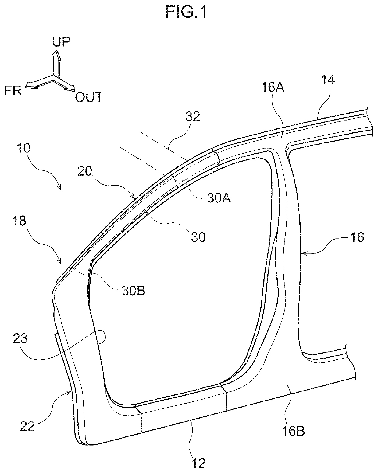
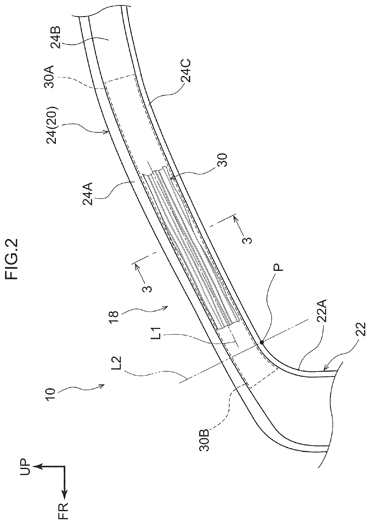
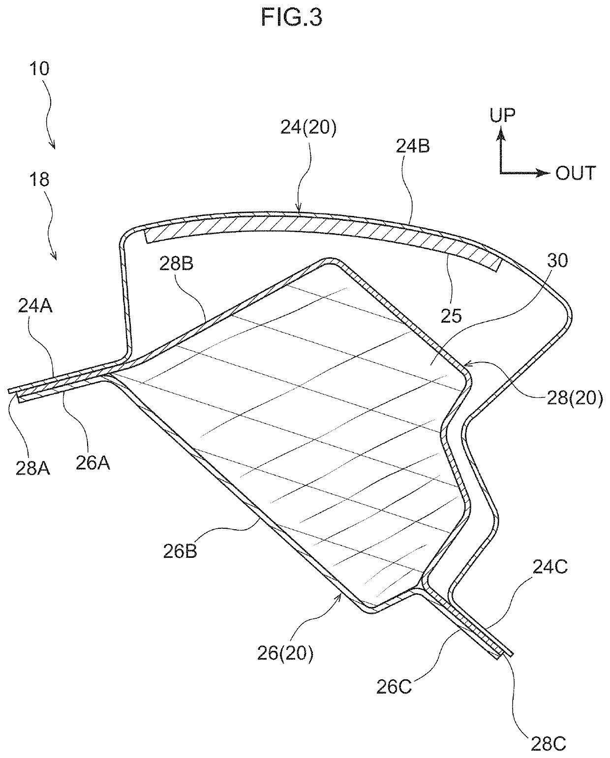
[0020]As illustrated in FIG. 1, a side section of a vehicle 10 applied with the vehicle side section structure is configured including a rocker 12, a roof side rail 14, a center pillar 16, and a front pillar 18. Note that although FIG. 1 only illustrates a vehicle side section on the vehicle left side and omits...

second exemplary embodiment

[0042]Explanation follows regarding a vehicle side section structure according to a second exemplary embodiment, with reference to FIG. 4. Note that similar configuration to the first exemplary embodiment is appended with the same reference numerals, and explanation thereof is omitted as appropriate.

[0043]As illustrated in FIG. 4, the front pillar 18 is provided to a side section of a vehicle 40 applied with the vehicle side section structure according to the present exemplary embodiment. A reinforcing member 42 is provided inside a cross-section of the front pillar 18.

[0044]Note that the axial center direction of the tree rings of the reinforcing member 42 of the present exemplary embodiment is oriented in a direction running along the length direction of the front pillar 18, similarly to in the first exemplary embodiment. Namely, the axial center of the tree rings of the reinforcing member 42 extend along the imaginary line L1 extending along the length direction of the front pill...


PUM


Abstract

A vehicle side section structure includes a pair of front pillars that are respectively provided at both vehicle width direction sides of a vehicle front section so as to extend along a vehicle vertical direction, and a reinforcing member formed of wood and is provided inside a cross-section of at least one of the pair of front pillars, an axial center direction of tree rings of the reinforcing member being oriented in a direction running along a length direction of the at least one front pillar.

Description

BACKGROUNDTechnical Field[0001]The present disclosure relates to a vehicle side section structure.Related Art[0002]Japanese Patent Application Laid-Open (JP-A) No. 2014-159187 discloses a reinforcing device that reinforces a front pillar. The reinforcing device includes a frame provided inside the front pillar. The front pillar is reinforced by fixing plural foamed bodies with the same shape as each other to the frame.[0003]In the structure described in JP-A No. 2014-159187, reinforcing the front pillar using the foamed bodies enables an increase in weight to be suppressed in comparison to cases in which a metal reinforcing member is employed. However, the plural foamed bodies are disposed with spacings therebetween, and so there is a possibility than collision load input to the front pillar in a head-on collision might not be dispersed, resulting in localized deformation of the front pillar.SUMMARY[0004]The present disclosure provides a vehicle side section structure that may suppr...

Claims


Application Information

Patent Timeline
IPC IPC(8): B62D29/02B62D25/04B62D21/15
CPCB62D21/152B62D29/02B62D25/04B62D21/157
Inventor TAKAYANAGI, JUNICHIMIURA, TOSHIHISA
Owner TOYOTA JIDOSHA KK
Learn More