Mechanical seal with high pressure high temperature secondary seal

a mechanical seal and high temperature technology, applied in the direction of engine seals, mechanical apparatus, engine components, etc., can solve the problems of not being able to permanently fix unable to achieve the effect of permanent fixing of the seal face to the shaft and housing, and using a secondary seal that includes a gasket and/or o-ring, etc., to achieve the effect of simple design, extended the operating temperature range of mechanical seals, and easy installation and removal

Active Publication Date: 2019-12-19
FLOWSERVE PTE LTD
View PDF10 Cites 0 Cited by
  • Summary
  • Abstract
  • Description
  • Claims
  • Application Information

AI Technical Summary

Benefits of technology

[0011]A high temperature, high pressure secondary seal design is disclosed that is simple in design (at least compared to a metallic bellows seal), easy to install and remove, extends the operating temperature range of a mechanical seal beyond existing limits, and, in embodiments, facilitates axial movement of an associated seal face. The novel secondary seal design includes an annular sealing gasket and a backing plate that surround an underlying cylind...

Problems solved by technology

Generally, this is such a small amount that if the leaked fluid is a liquid, it tends to evaporate rather than pool, and therefore remains unnoticed.
Generally, it is not practical to permanently fix the seal faces to the shaft and housing.
For this reason, the use of a secondary seal that includes a gasket and/or O-ring can limit the maximum temperature at which a mechanical seal can operate, due to te...

Method used


Image

  • Mechanical seal with high pressure high temperature secondary seal
  • Mechanical seal with high pressure high temperature secondary seal
  • Mechanical seal with high pressure high temperature secondary seal

Examples


Embodiment Construction

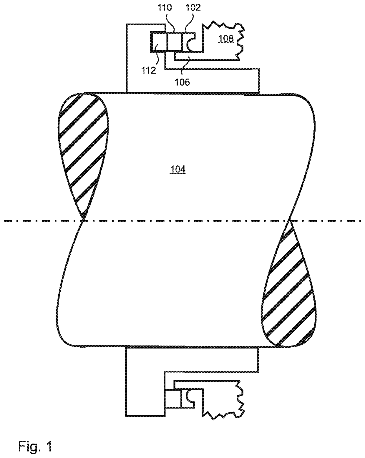
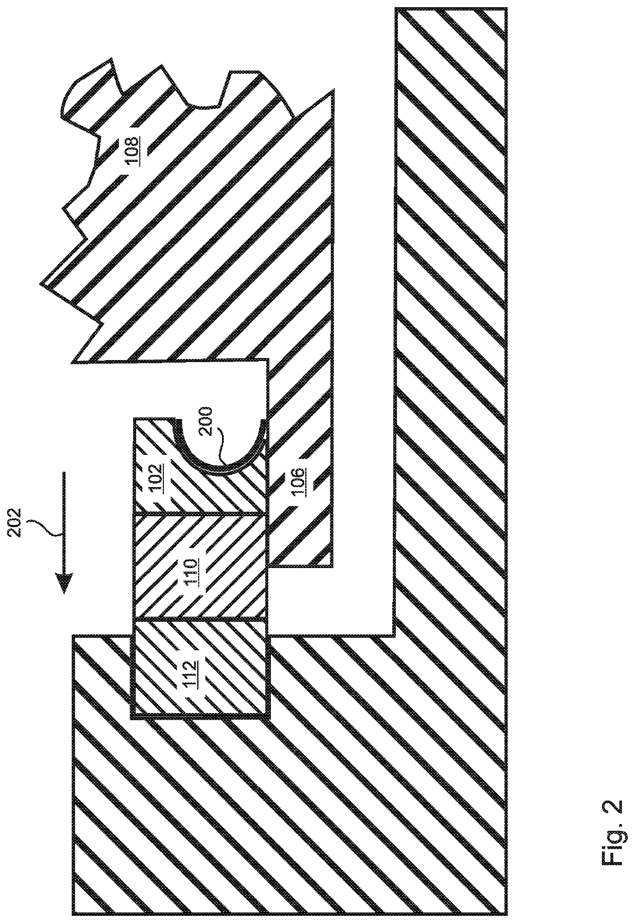
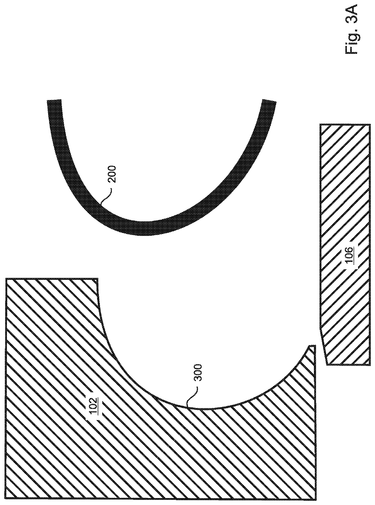
[0044]The present invention is a high temperature, high pressure static seal design that extends the operating temperature range of a mechanical seal beyond existing limits, and which preferably facilitates axial movement of an associated seal face. With reference to FIGS. 1 and 2, the novel seal design includes an annular sealing gasket 200 and a backing plate 102 that surround an underlying cylindrical sealing surface, which can be the outer surface of the rotating shaft 104 or of a collar 106 that surrounds the rotating shaft and is fixed to either the shaft 104 or to the housing 108. In the embodiment of FIGS. 1 and 2, the sealing surface is a collar 106 that surrounds the shaft 104, but is static and fixed to the housing 108. The backing plate 102 is sealed to an associated seal face 110, which in FIGS. 1 and 2 is the static seal face 110, which forms a seal with the other seal face 112, which in FIGS. 1 and 2 is the rotating seal face 112. Although no specific mechanism is sho...


PUM


Abstract

A secondary seal of a mechanical seal comprises an annular sealing gasket and backing plate surrounding a cylindrical sealing surface, all of which can be made of the same metallic material. The gasket is C-shaped in cross section, and is axially pressed during operation into a C-shaped groove formed in the backing plate, the groove being shallower and larger in inner diameter than the gasket, so that the gasket, when pressed into the groove, deforms radially inward and seals against both the backing plate and the sealing surface. The contact area between the gasket and sealing surface increases with pressure. In embodiments, when the pressure is released, the gasket retracts from the sealing surface, allowing easy disassembly and allowing axial movement of the gasket and backing plate. Highly polished surfaces of the gasket and sealing surface can allow axial motion thereof during operation to maintain the seal face gap.

Description

FIELD OF THE INVENTION[0001]The invention relates to rotating shaft seals, and more particularly, to rotating shaft mechanical seals.BACKGROUND OF THE INVENTION[0002]A mechanical seal is a seal that is formed by close proximity of two flat, annular, non-contacting seal faces, usually referred to as a static seal face and a rotating seal face, in that one face is typically static and sealed to a housing, while the other face is sealed to a rotating shaft and rotates with the shaft. The two seal faces are annular, and coaxial with the rotating shaft, whereby the long axis of the shaft is also the common axis of the annular seal faces.[0003]Traditionally the two seal faces are lapped flat to a very high degree of flatness, which allows the faces to be configured in a parallel relationship whereby they are not physically in contact with each other, but are separated by a gap that can be as narrow as one micron or less. The gap itself is also annular in shape, and shares a common central...

Claims


Application Information

Patent Timeline
IPC IPC(8): F16J15/36F16J15/28F16J15/16F16J15/34
CPCF16J15/363F16J15/3472F16J15/3452F16J15/38F16J15/3464F16J15/344F16J15/3448F16J15/3228
Inventor HAMILTON, ERICNELSON, DANIEL
Owner FLOWSERVE PTE LTD
Why Eureka
Try Eureka