Access method in communication system and device for performing same
a communication system and access method technology, applied in the direction of wireless communication, electrical equipment, connection management, etc., can solve the problem of inefficiency of random access procedure, and achieve the effect of improving the performance of the communication system
- Summary
- Abstract
- Description
- Claims
- Application Information
AI Technical Summary
Benefits of technology
Problems solved by technology
Method used
Image
Examples
first embodiment
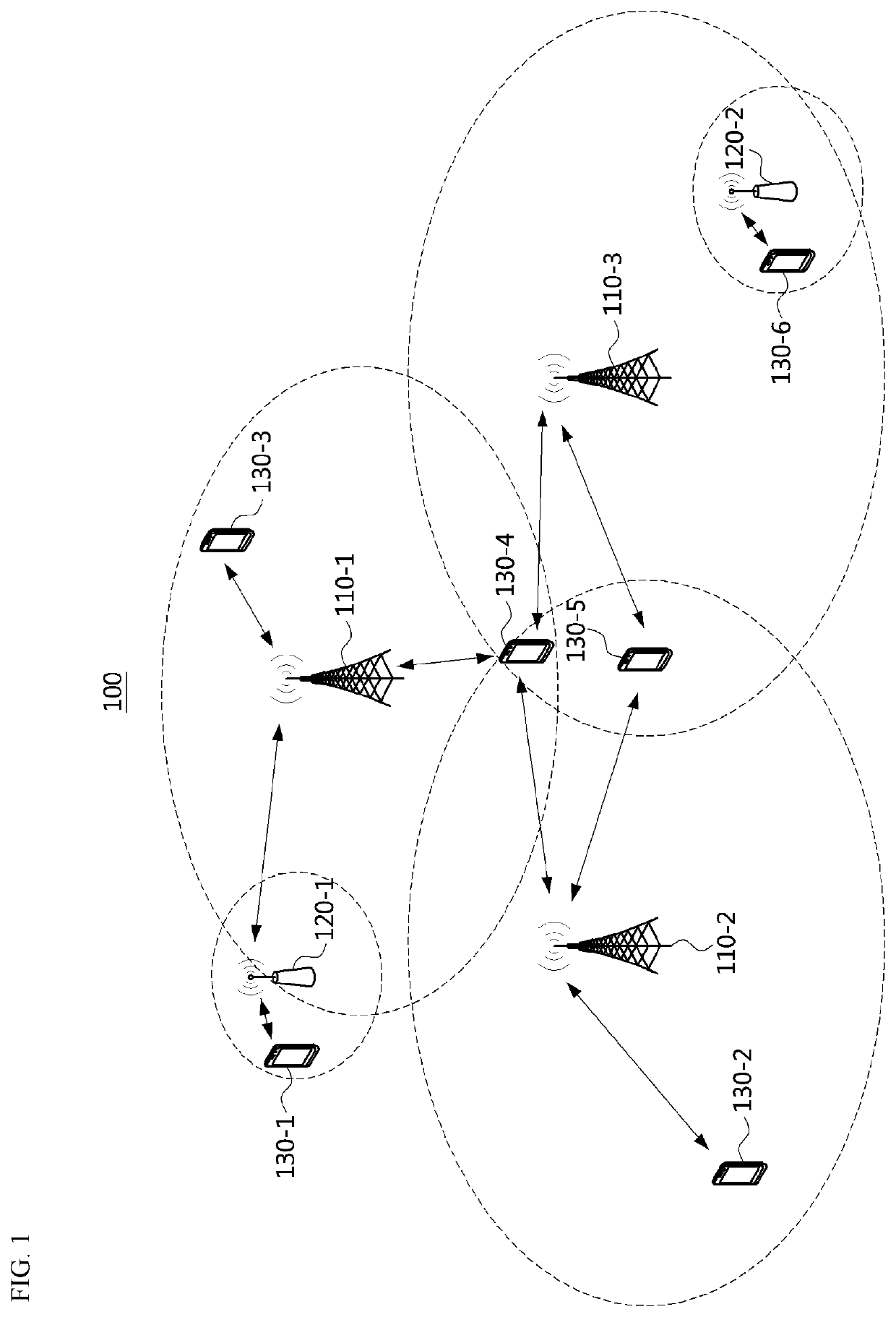
[0057]FIG. 1 is a conceptual diagram illustrating a cellular communication system.
[0058]Referring to FIG. 1, a communication system 100 may comprise a plurality of communication nodes 110-1, 110-2, 110-3, 120-1, 120-2, 130-1, 130-2, 130-3, 130-4, 130-5, and 130-6. Also, the communication system 100 may comprise a core network (e.g., a serving gateway (S-GW), a packet data network (PDN) gateway (P-GW), a mobility management entity (MME), and the like).
[0059]The plurality of communication nodes may support 4G communication (e.g., long term evolution (LTE), LTE-advanced (LTE-A)), or 5G communication defined in the 3rd generation partnership project (3GPP) standard. The 4G communication may be performed in a frequency band below 6 gigahertz (GHz), and the 5G communication may be performed in a frequency band above 6 GHz. For example, for the 4G and 5G communications, the plurality of communication nodes may support at least one communication protocol among a code division multiple acces...
second embodiment
[0100]FIG. 5 is a sequence chart illustrating a random access procedure in a communication system. In the following description of the embodiment of FIG. 5, the description overlapping with FIG. 4 is omitted.
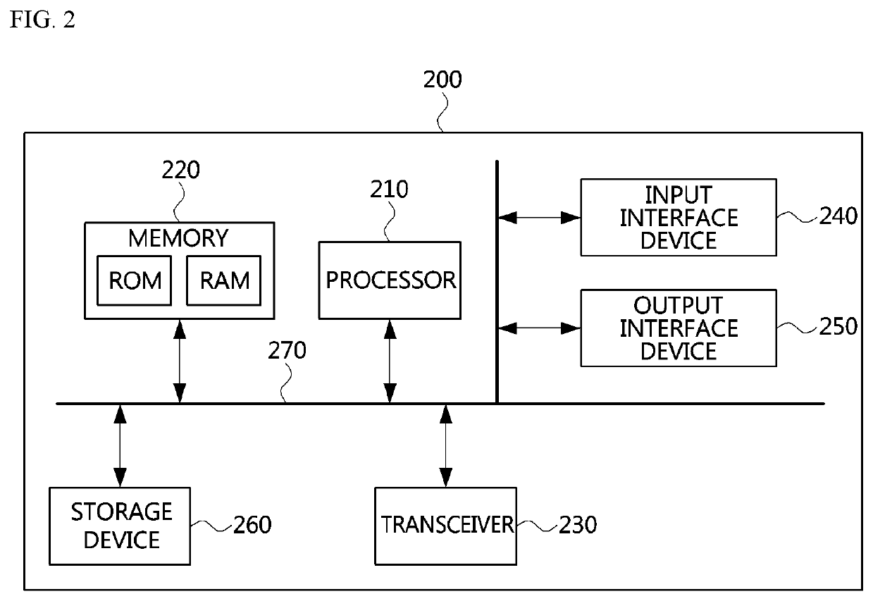
[0101]Referring to FIG. 5, a communication system may include a terminal 410, a first base station 420, and the like. Each of the terminal 410 and the first base station 420 may be configured to be the same as or similar to the communication node 200 shown in FIG. 2. In a step S510, the terminal 410 may receive common information from the first base station 420. The terminal 410 may perform a random access procedure with the first base station 420 using the common information received from the first base station 420. For example, the terminal 410 may transmit a random access preamble (RA MSG1) to the first base station 420 by using a resource indicated by the common information (S520). The first base station 420 may receive the random access preamble (RA MSG1) from the terminal ...
third embodiment
[0135]FIG. 8 is a conceptual diagram illustrating an uplink message.
[0136]Referring to FIG. 8, the uplink message (RA MSG3) may include a terminal identifier field, a FI field, a reserved field R, an RA attempt reason field, and a terminal information field. Here, the uplink message (RA MSG3) may not include the first field IDI. In this case, the terminal 410 may use radio resources (e.g., radio resources allocated according to the size of the identifier of the terminal 410) allocated based on the common information obtained in the step S410 to transmit the random access preamble (RA MSG1) in the step S420. For example, the terminal 410 may transmit the random access preamble (RA MSG1) using different radio resources for each of a short ID of the terminal 410 and a long ID of the terminal 410. In the step S420, the first base station 420 may determine the size of the identifier (e.g., short ID or long ID) of the terminal 410 based on the radio resources used for the transmission of ...
PUM
 Abstract
Description
Claims
Application Information
 - R&D
- Intellectual Property
- Life Sciences
- Materials
- Tech Scout
- Unparalleled Data Quality
- Higher Quality Content
- 60% Fewer Hallucinations
Browse by: Latest US Patents, China's latest patents, Technical Efficacy Thesaurus, Application Domain, Technology Topic, Popular Technical Reports.
© 2025 PatSnap. All rights reserved.Legal|Privacy policy|Modern Slavery Act Transparency Statement|Sitemap|About US| Contact US: help@patsnap.com


