Fiber-Bound Engineered Materials Formed Using Engineered Scrims

a technology of engineered textiles and fiber binding, which is applied in the direction of fastenings, uppers, bootlegs, etc., can solve the problem of creating a non-uniform engineered material

Pending Publication Date: 2019-12-26
NIKE INC
View PDF0 Cites 25 Cited by
  • Summary
  • Abstract
  • Description
  • Claims
  • Application Information

AI Technical Summary

Benefits of technology

[0003]Aspects hereof provide a fiber-bound engineered material, and methods of making the same, that provides an intended characteristic at an intended relative location. A fiber layer is entangled with additional fibers in a manner that creates a non-uniform engineered material. That is, a fiber layer is entangled with additional fibers in a manner that creates an engineered material having at least one non-uniform functional characteristic. Lack of uniformity in a fiber-bound engineered material may be accomplished through manipulation of the fibers forming the fiber layer, manipulation of additional fibers, and / or through fiber-binding a scrim. The fiber layer binds with additional fibers through entanglement such that a mechanical connection between the entangled fibers is created. This entanglement allows the fibers to bind without supplemental adhesives, interlacing, or connections. Variations in the fibers and / or inclusion of scrim materials prior to entanglement allows for an intended characteristic (e.g., a functional characteristic) at an intended relative location (e.g., a position determined by an article to be formed therefrom).

Problems solved by technology

A fiber layer is entangled with additional fibers in a manner that creates a non-uniform engineered material.
That is, a fiber layer is entangled with additional fibers in a manner that creates an engineered material having at least one non-uniform functional characteristic.

Method used


Image

  • Fiber-Bound Engineered Materials Formed Using Engineered Scrims
  • Fiber-Bound Engineered Materials Formed Using Engineered Scrims
  • Fiber-Bound Engineered Materials Formed Using Engineered Scrims

Examples


Embodiment Construction

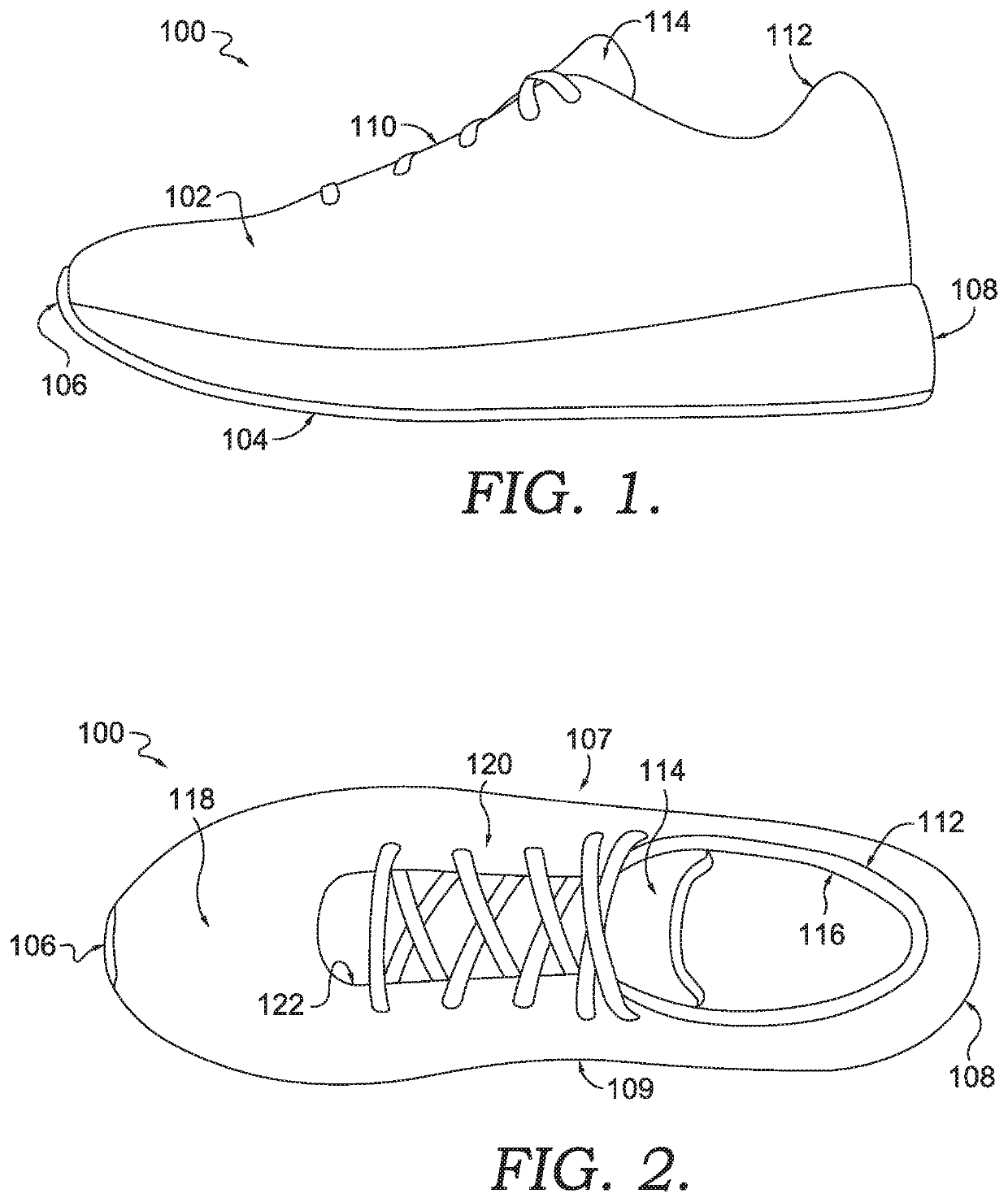
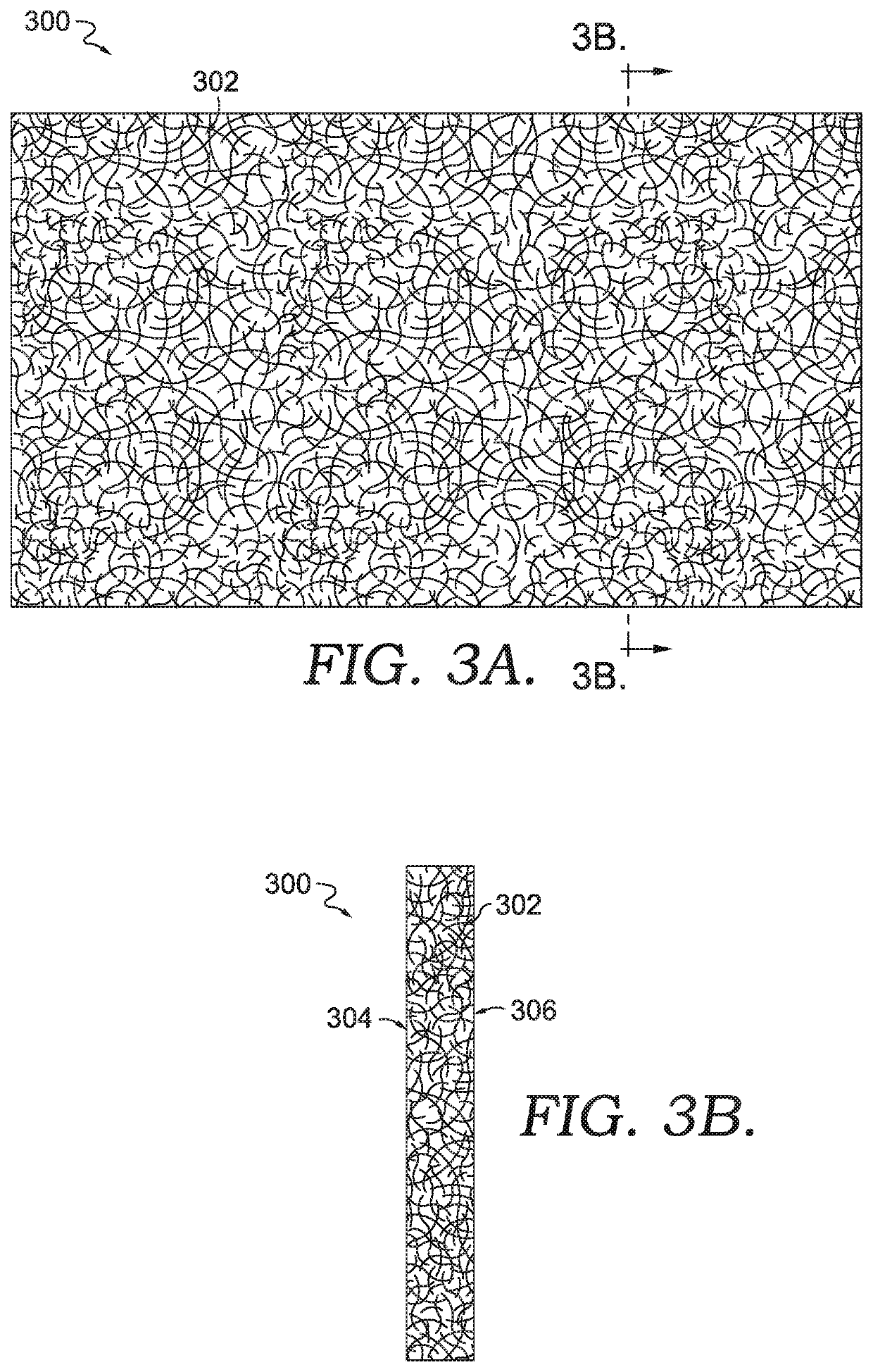
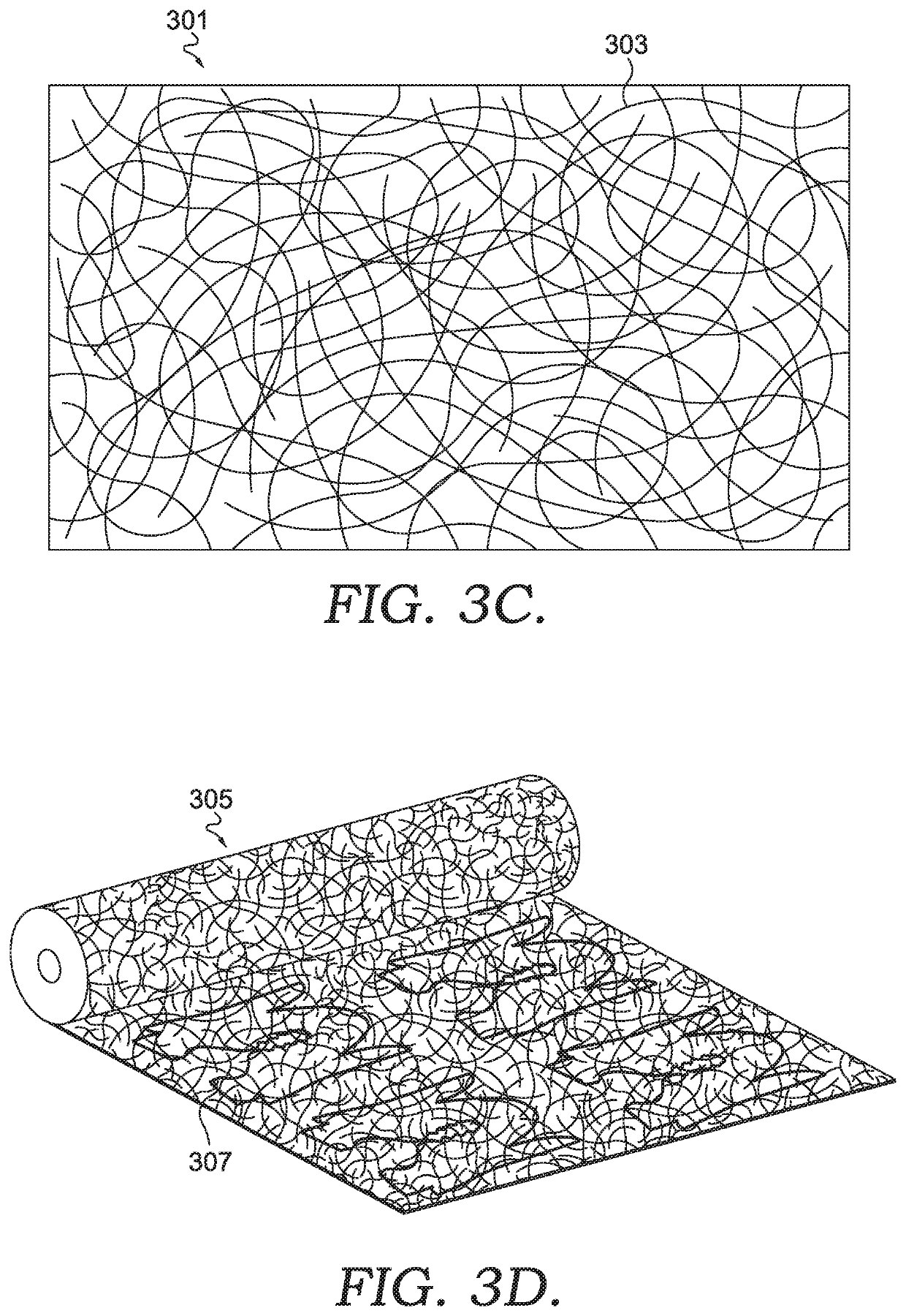
[0073]Fiber binding is a process in which fibers from one or more fiber layers are entangled to form a complex composite material that is engineered for an article. The engineered material may have structures entrapped within the fiber layers to achieve an engineered quality for a specific article, such as a shoe or piece of apparel. In the context of a sport shoe, the fiber-bound material may include, by way of example only, an entrapped high-tensile cable element to transfer lace loads from a throat to a sole, entrapped foam-structure elements that provide padding in a heel collar, entrapped fusible-material elements that form into a rigid heel stay and / or a water-resistant membrane in the toe box, and / or entrapped hardware elements that serve as a lacing structure. All of the elements / components are integral to the engineered material as they are entangled with and / or by the one or more fiber layers without additional cutting, fusing, or sewing operations being performed.

[0074]Th...


PUM

PropertyMeasurementUnit
widthaaaaaaaaaa
widthaaaaaaaaaa
widthaaaaaaaaaa

Abstract

A fiber bound engineered material is provided that imparts an intended characteristic at an intended relative location. A fiber layer is entangled with additional fibers in a manner to create a non-uniform engineered material. The lack of uniformity of a fiber bound engineered material may be accomplished through manipulation of the fibers and/or through fiber binding a scrim. The fiber layer binds with additional fibers through entanglement such that a mechanical connection between the entangled fibers is provided. This entanglement allows the fibers to bind without supplemental adhesives, interlacing, or connections. Variations in the fibers and/or inclusion of scrim materials prior to entanglement allows for an intended characteristic (e.g., a functional characteristic) at an intended relative location (e.g., a position determined by an article to be formed therefrom).

Description

FIELD OF THE INVENTION[0001]Aspects hereof relate to engineered textiles having fiber binding. Aspects further relate to engineered textiles formed utilizing an engineered scrim.BACKGROUND OF THE INVENTION[0002]Stock materials, such as rolled goods, traditionally have a uniform functional characteristic throughout the material. To form engineered articles from the stock materials, the stock materials may be cut into individual pieces and layered and / or combined to build the engineered article. The layering and combining of discrete pieces can increase costs, increase bulk, increase waste, and limit design options for the resultant engineered article.SUMMARY OF THE INVENTION[0003]Aspects hereof provide a fiber-bound engineered material, and methods of making the same, that provides an intended characteristic at an intended relative location. A fiber layer is entangled with additional fibers in a manner that creates a non-uniform engineered material. That is, a fiber layer is entangle...

Claims


Application Information

Patent Timeline
Patent Type & Authority Applications(United States)
IPC IPC(8): A43B1/00B32B5/02B32B5/06B32B5/10B32B5/26A43B1/04A43B23/02
CPCA43B1/0027B32B5/024B32B2437/02A43B23/0235B32B5/26B32B5/026A43B1/04B32B5/06B32B5/028A43B23/026B32B5/10A43B1/0072A43B23/0265B32B5/022A43B1/02A43B23/0205A43C5/00
Inventor DUA, BHUPESHGREENE, PAMELA S.KILGORE, BRUCE J.RUSHBROOK, THOMAS J.
Owner NIKE INC
Why Eureka
Try Eureka