
System and method for hydro-demolition of concrete structures

a concrete structure and hydro-demolition technology, applied in the field of systems and methods for demolition of concrete structures, can solve the problems of significant danger for workers tasked with demolition projects, significant risk to workers, and high cost and time-consuming

Inactive Publication Date: 2020-01-02
STRUCTURAL GRP
View PDF0 Cites 6 Cited by
  • Summary
  • Abstract
  • Description
  • Claims
  • Application Information

AI Technical Summary

Benefits of technology

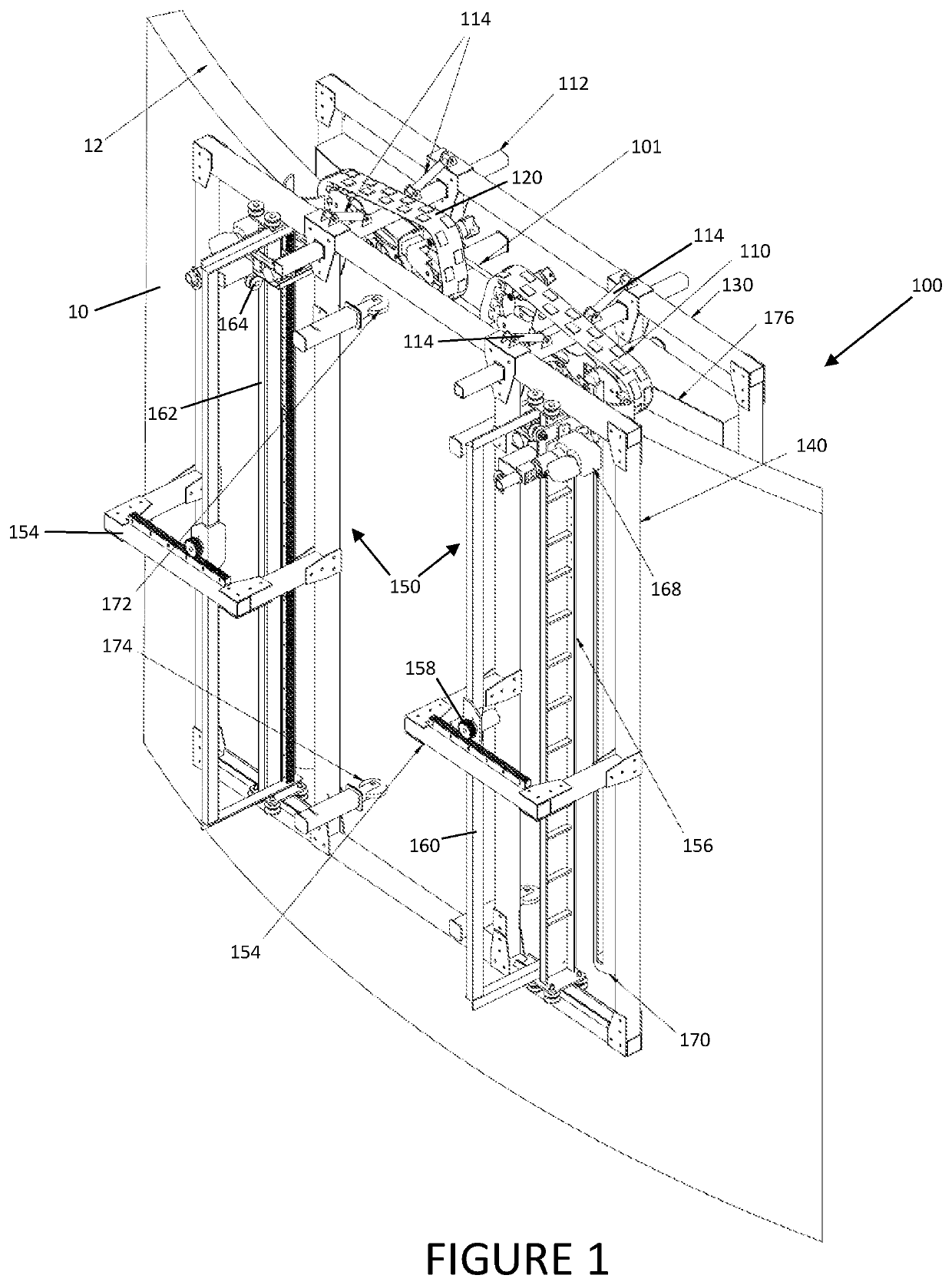
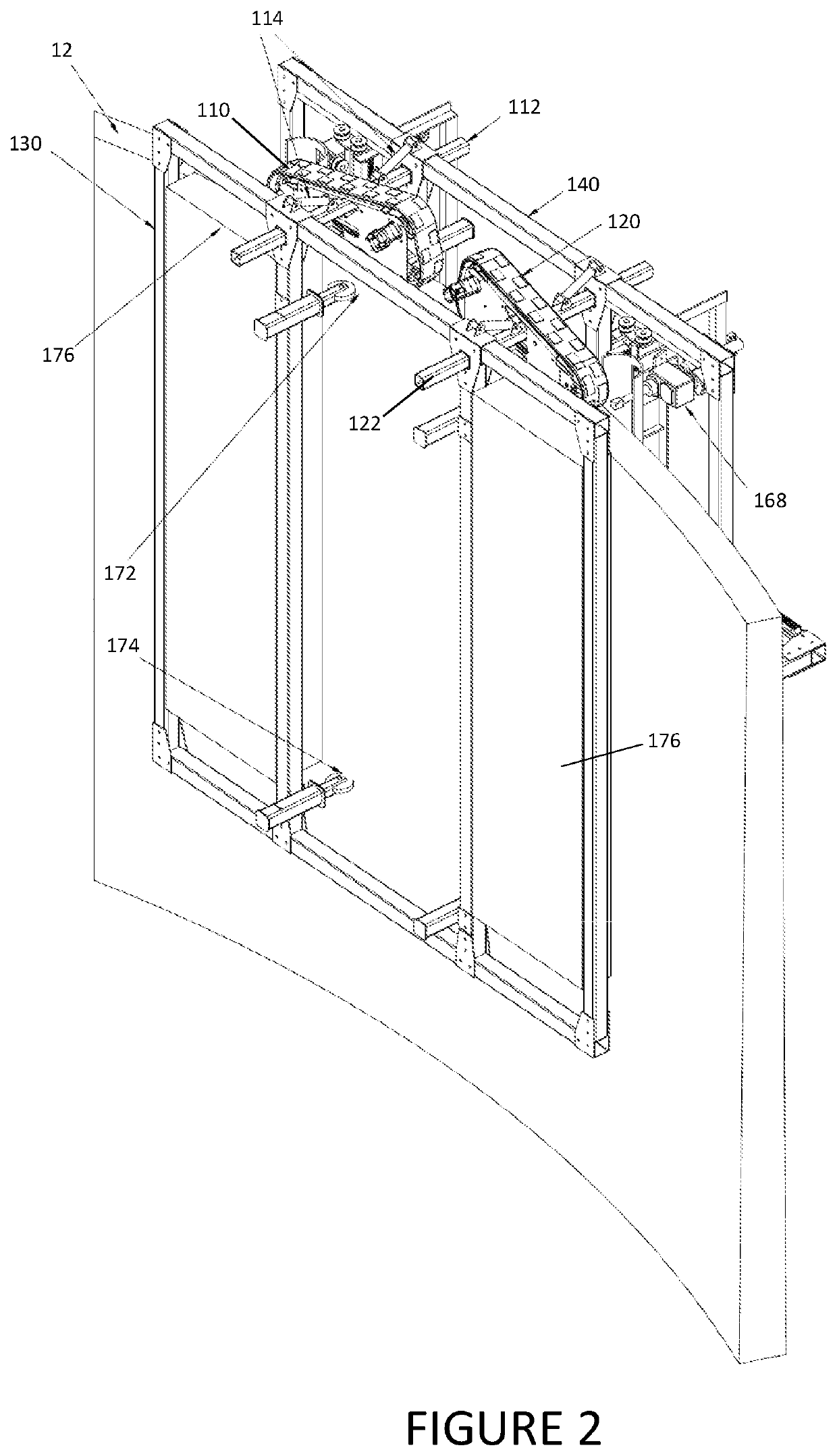
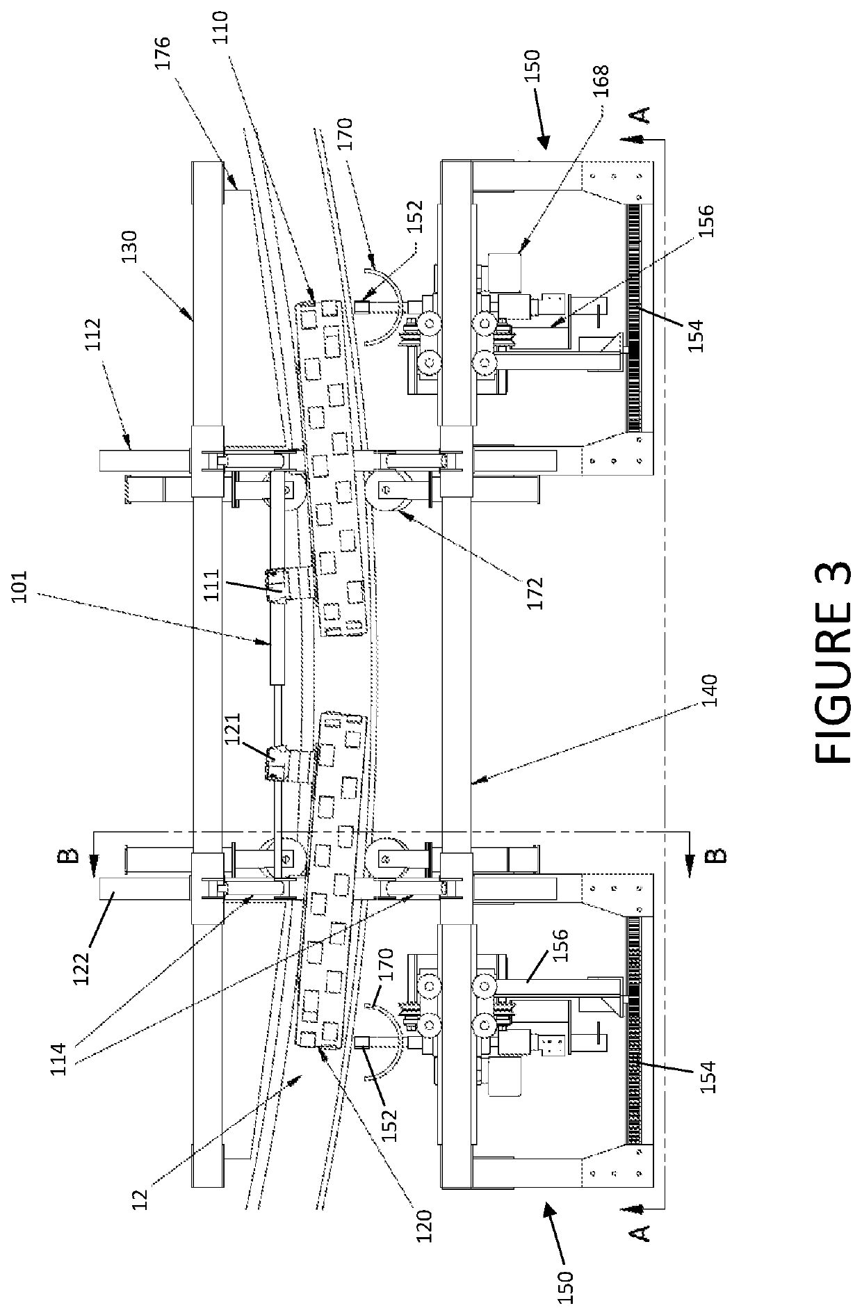
The patent describes a system and method for demolishing vertical concrete structures using a moveable concrete cutting vehicle. This vehicle includes a carriage that rides or rolls along the top surface of the vertical concrete structure and carries a cutting assembly that can make horizontal and downwardly angled cuts through the entire width of the concrete wall. The carriage can then be moved along the top surface of the concrete structure, and small blocks of concrete can be tipped off the remaining structure to fall to the ground. The system can be used to demolish concrete structures from the top down. The technical effect of this patent is a more efficient and precise method for demolishing vertical concrete structures that reduces the amount of material waste and noise.

Problems solved by technology

The demolition of vertical concrete structures, such as chimneys, silos, stacks, and the like, has been previously carried out in a variety of ways, and typically involve manual demolition, which given the extreme height of such structure, can entail significantly dangerous operations.
However, such previously known methods are expensive and lengthy to carry out, and often carry significant risk to the workers tasked with performing the demolition project.

Method used


Image

  • System and method for hydro-demolition of concrete structures
  • System and method for hydro-demolition of concrete structures
  • System and method for hydro-demolition of concrete structures

Examples


Embodiment Construction

[0015]The invention may be understood by referring to the following description and accompanying drawings. This description of an embodiment, set out below to enable one to practice an implementation of the invention, is not intended to limit the preferred embodiment, but to serve as a particular example thereof. Those skilled in the art should appreciate that they may readily use the conception and specific embodiments disclosed as a basis for modifying or designing other methods and systems for carrying out the same purposes of the present invention. Those skilled in the art should also realize that such equivalent assemblies do not depart from the spirit and scope of the invention in its broadest form.

[0016]Descriptions of well-known functions and structures are omitted to enhance clarity and conciseness. The terminology used herein is for the purpose of describing particular embodiments only and is not intended to be limiting of the present disclosure. As used herein, the singul...


PUM


Abstract

Disclosed is a system and method for the demolition of vertical concrete structures. A moveable concrete cutting vehicle includes a carriage adapted to move along the top surface of the vertical concrete structure that is to be demolished. The carriage carries a cutting assembly that is moveable in at least two directions, such as a vertical direction and a slightly downwardly angled circumferential direction, which cutting assembly is positioned to make cuts through the entire width of the concrete wall of the vertical concrete structure. After a series of cuts have been performed, the carriage may be moved along the top, horizontal rim of the vertical concrete structure, and separable concrete blocks that have been formed in the previously processed region may be tipped off of the remaining vertical concrete structure to fall to the ground. Such process may continue with the carriage carrying the concrete cutting vehicle progressively downward and around the vertical concrete structure, allowing small, block-shaped sections of the concrete structure to be tipped into the concrete structure until the entire concrete structure has been demolished.

Description

CROSS REFERENCE TO RELATED APPLICATION[0001]This application claims the benefit of U.S. Provisional Application No. 62 / 693,099 titled “System and Method for Hydro-Demolition of Concrete Structures,” filed Jul. 2, 2018 by the Applicant herein, which application is incorporated herein by reference in its entirety.FIELD OF THE INVENTION[0002]This invention relates generally to systems and methods for demolition of concrete structures, and more particularly to systems and methods of vertically progressive hydro-demolition of vertical concrete structures.BACKGROUND[0003]The demolition of vertical concrete structures, such as chimneys, silos, stacks, and the like, has been previously carried out in a variety of ways, and typically involve manual demolition, which given the extreme height of such structure, can entail significantly dangerous operations. Demolition methods have included controlled explosives (particularly where there is a wide, open area surrounding the structure into which...

Claims


Application Information

Patent Timeline
IPC IPC(8): E04G23/08B26F3/00
CPCB26F3/004E04G23/081E04G2023/087
Inventor JACKSON, BARRYDICKSON, SAM
Owner STRUCTURAL GRP
Learn More