
Water storage tank type steel structural dam

A technology for steel dams and water storage tanks, applied in dams, gravity dams, etc., can solve the problems of high terrain and geological requirements, high cost of steel dams, and large sand and gravel materials, and achieve low cost, increased self-weight, and long service life Effect

Active Publication Date: 2011-11-23
NORTH CHINA UNIV OF WATER RESOURCES & ELECTRIC POWER
View PDF4 Cites 5 Cited by
  • Summary
  • Abstract
  • Description
  • Claims
  • Application Information

AI Technical Summary

Problems solved by technology

The cost of steel dam is high, the technical requirements are high, and the construction is difficult. In order to improve the supporting force of the steel structure, a more complicated truss structure is required. Constructing concrete slopes requires high topography and geology
The dam bodies of earth dams and rockfill dams occupy a large amount of sand and gravel, and the construction period is long, requiring a special drainage and anti-seepage system

Method used


Image

  • Water storage tank type steel structural dam
  • Water storage tank type steel structural dam
  • Water storage tank type steel structural dam

Examples


Embodiment 1

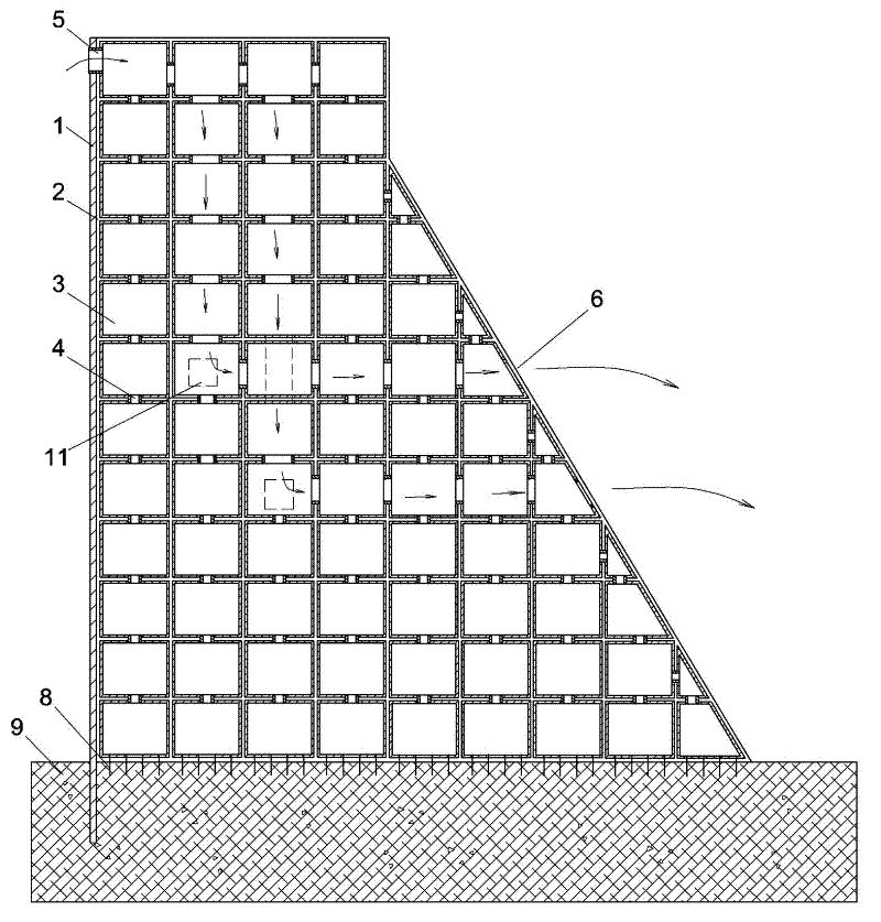
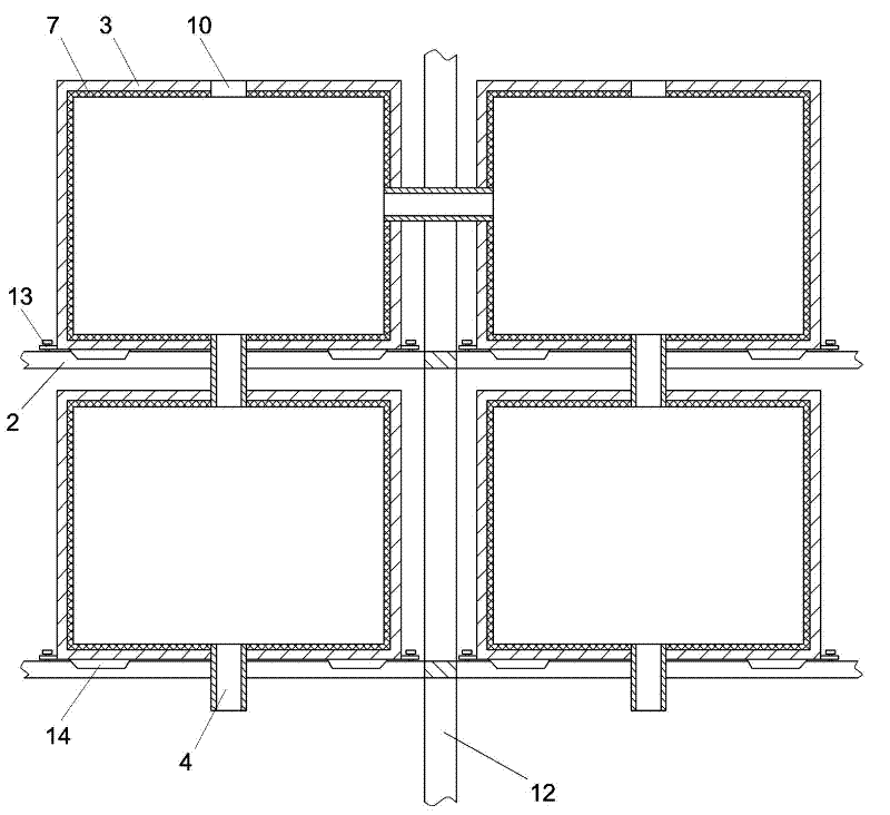
[0018] A water storage tank type steel structure dam comprises a truss structure dam body 2 and a steel structure water retaining panel 1 . The lower end of the truss structure dam. Each unit cell of the truss structure siege is fixedly installed with matching water 3 respectively, and each water tank on the same vertical line is connected to each other, and all adjacent water tanks can also be connected to each other. The water tank at the upper end of the truss structure is provided with a water inlet 5, and a water pump for injecting water into the water tank is installed at the upper end of the truss structure. The truss structure dam 2, the steel structure panel 1, the water tank 3 and the connecting bolts are supplemented with a layer of anti-corrosion coating polyurea material.

[0019] figure 2 Among them, a plastic plate 7 is also set and sealed inside each water tank.

[0020] figure 1 There are multiple rows (on the same vertical line) of water tanks connected ...

Embodiment 2

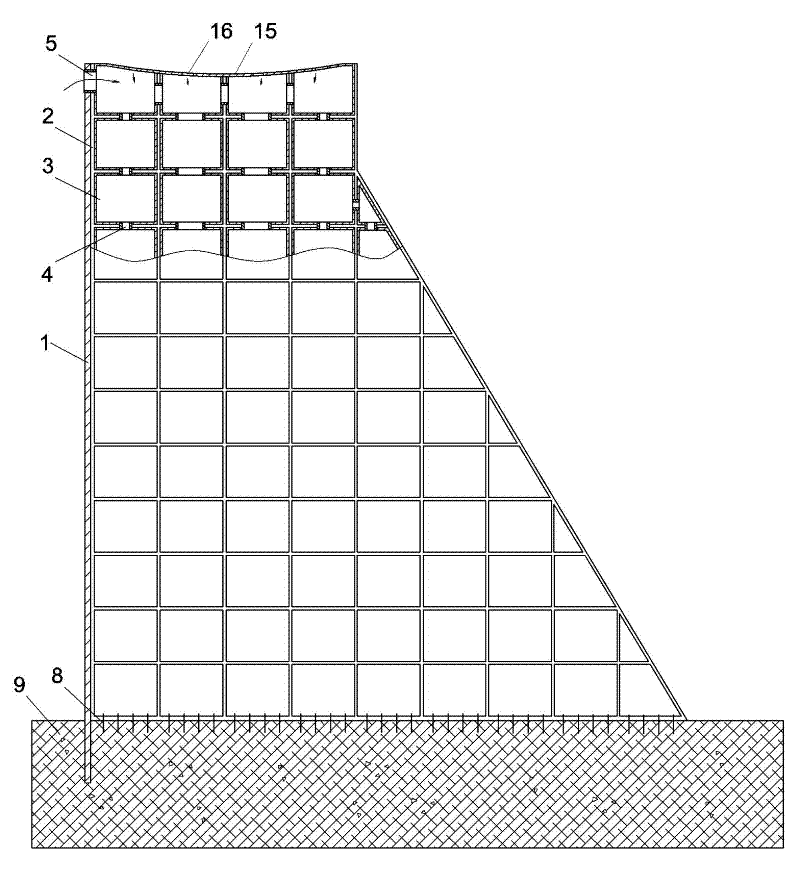
[0022] Embodiment three: see Figure 4 , the content is basically the same as that of Embodiment 1, and the similarities will not be repeated. The difference is that a steel plate 1' is fixed on the back water surface of the truss structure dam body, and the distribution of the water retaining surface steel plate 1 and the back water surface steel plate 1' is consistent with the concrete bearings on both sides. The platform is sealed to form a water-accommodating cavity. The cavity is filled with water so that part of the truss is located in the water injection cavity and is aided by a layer of anti-corrosion polyurea material on the truss and all steel structural panels.

Embodiment 3


PUM


Abstract

The invention relates to a water storage tank type steel structural dam, which comprises a truss structural dam body and a steel structural water retaining panel, wherein the lower end of the truss structural dam body is fixed on an inner concrete bearing platform of a riverbed, the steel structural water retaining panel is fixed on the water retaining surface of the truss structural dam body, a matched water tank is fixedly arranged in each cell encircled by the truss structure, the water tanks are communicated with one another, and the water tank at the upper end of the truss structure is provided with a water inlet and a water pump. The water storage tank type steel structural dam has simple, stable and reliable structure and simultaneously has the advantages of a steel structural dam and a gravity dam; and the lower end and two sides of the truss of the water storage tank type steel structural dam are easily fixed with the bearing platform and the side slope, so that the water storage tank type steel structural dam is easy in construction and maintenance. The water tanks can be industrially produced and constructed on site, so the construction efficiency is high. The dam has long service life and low cost, and is very suitable for popularization and implementation.

Description

[0001] technical field [0002] The invention relates to a water tank dam in the field of water conservancy and hydropower engineering, in particular to a water storage tank type steel structure dam. Background technique [0003] At present, there are many kinds of dams in the field of water conservancy technology, but most of them have the disadvantages of difficult construction, high technical requirements and long construction period. The cost of steel dam is high, the technical requirements are high, and the construction is difficult. In order to improve the supporting force of the steel structure, a more complicated truss structure is required. Constructing concrete slopes requires high topography and geology. The dam bodies of earth dams and rockfill dams occupy a large amount of sand and gravel, and the construction period is long, requiring special drainage and anti-seepage systems. Contents of the invention [0004] In order to overcome the deficiencies in the p...

Claims


Application Information

Patent Timeline
IPC IPC(8): E02B7/10
Inventor 魏群刘尚蔚张国新高阳秋晔娄健康黄丹璐
Owner NORTH CHINA UNIV OF WATER RESOURCES & ELECTRIC POWER
Learn More