
Clamp for regular polygonal pipe cutting

A regular polygon and fixture technology, which is applied in the field of fixtures for regular polygon pipe cutting, can solve problems such as burrs on the bottom edge, complex fixture structure, and cumbersome operation, etc., achieve good axial clamping effect, simple fixture structure, and ensure cutting quality effect

Pending Publication Date: 2019-04-23
VICHNET COMM SCI & TECH
View PDF0 Cites 0 Cited by
  • Summary
  • Abstract
  • Description
  • Claims
  • Application Information

AI Technical Summary

Problems solved by technology

[0003] In the early days, some people supported and fixed regular polygonal tubes for cutting, but the quality and efficiency were certainly not ideal.
Later, some clamps for fixing and clamping regular polygonal tubes appeared, but most of them are clamped from the side. The cut section will first affect the cutting of the bottom edge due to gravity drooping and is prone to burrs. After cutting, it will fall on the base. Noise or damage to the tube or base on the seat; and generally there are only clamps for square tubes; moreover, the prior art clamps for cutting square tubes have complex structures, cumbersome operations, and poor reliability

Method used


Image

  • Clamp for regular polygonal pipe cutting
  • Clamp for regular polygonal pipe cutting
  • Clamp for regular polygonal pipe cutting

Examples


Embodiment Construction

[0025]The specific embodiments of the present invention will be further described below in conjunction with the accompanying drawings. What needs to be declared here is that the descriptions of these embodiments are used to help understand the present invention, but are not intended to limit the present invention. In addition, the technical features involved in the various embodiments of the present invention described below may be combined with each other as long as they do not conflict with each other.

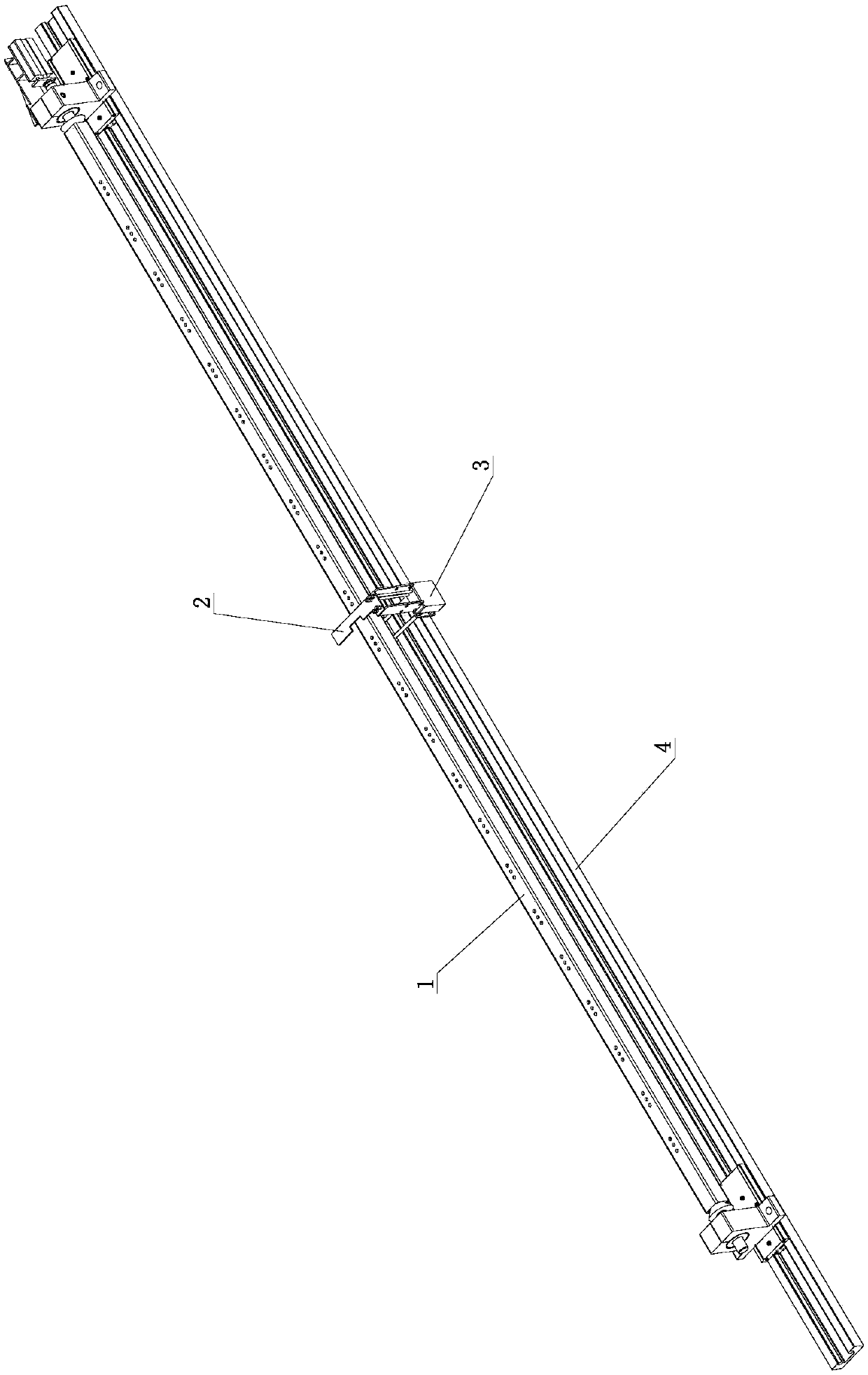
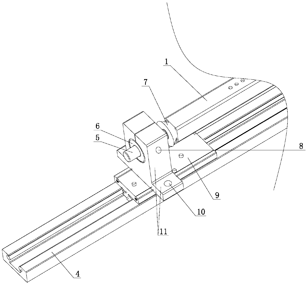
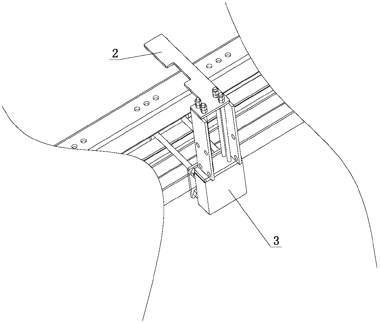
[0026] Such as figure 1 , figure 2 , image 3 , Figure 4 , Figure 5 shown

[0027] The jig used for cutting regular polygonal pipes of the present invention includes a base 4 extending along the length direction, and a slide rail is arranged on the base 4, and two slide seats are slidably fitted on the slide rail. It also includes a structure for positioning the sliding seat at any position in the length direction of the base.

[0028] The matching structure and po...


PUM


Abstract

The invention discloses a clamp for regular polygonal pipe cutting. The clamp comprises a base extending in a length direction and a structure enabling sliding seats to be positioned at any position in the length direction of the base; the base is provided with a sliding rail; the two sliding seats are matched on the sliding rail in a sliding manner, wherein first supporting seat is fixed on the first sliding seat, and the inner end, axially limited in a first shaft hole of the first supporting seat, of a first shaft is provided with a first ejection head abutting against one end of a regularpolygonal pipe to be cut; a second supporting seat is fixed on the second sliding seat, the inner end, slidably matched to the interior of a second shaft hole of the second supporting seat, of a second shaft is provided with a second ejection head which abuts against the other end of the regular polygonal pipe to be cut, and the first ejection head and the second ejection head are coaxial; and a linear drive device used for axially abutting against or axially loosening the second ejection head is fixed on the second supporting seat. The clamp can ensure the cutting quality of the pipe, avoidsnoise and damages on the pipe and the base as well as is good in axial clamping effect and strong in applicability.

Description

technical field [0001] The invention relates to the technical field of pipe processing equipment, in particular to a fixture for cutting regular polygonal pipes. Background technique [0002] Regular polygonal tubes refer to tubes with regular polygonal cross-sections, such as regular triangular tubes, square tubes, rectangular tubes, regular pentagonal tubes, regular hexagonal tubes, etc. The materials are generally metal tubes such as stainless steel tubes, aluminum alloy tubes, etc. There are also Adopt plastic tube. As it is used more and more widely and cutting processing is becoming more and more frequent, the traditional saw cutting method is rarely used, and oxygen cutting is generally used. Recently, laser cutting is also more common. [0003] In the early days, some people used hand support and fixed regular polygonal tubes for cutting, but the quality and efficiency were certainly not ideal. Later, some clamps for fixing and clamping regular polygonal tubes appe...

Claims


Application Information

Patent Timeline
Patent Type & Authority Applications(China)
IPC IPC(8): B23K26/70B23K26/38B23K37/04B23K101/06
CPCB23K26/38B23K26/702B23K37/0443
Inventor 吴伟国李瑞志
Owner VICHNET COMM SCI & TECH
Learn More