
Measurement Device, Electronic Apparatus And Measurement Method

Active Publication Date: 2020-01-02
SEIKO EPSON CORP
View PDF5 Cites 1 Cited by
  • Summary
  • Abstract
  • Description
  • Claims
  • Application Information

AI Technical Summary

Benefits of technology

The patent text describes a measurement device that uses multiple light sources to measure the spectral reflectivity of an object. The device has a spectroscopic measurement section that measures the light reflected by the object and a light source switching section that switches between the multiple light sources to measure the object with different combinations. An arithmetic section calculates the spectral reflectivity of the object based on the measured light with each combination. The device can also include a type discrimination section that can identify the type of object based on the spectral reflectivity. Overall, the device provides a more accurate and versatile way to measure the spectral reflectivity of objects.

Problems solved by technology

However, in the device described in Document 1, since the measurement object (a printing medium) is irradiated by the light from a single light source, there is a problem that the light intensity of the reflected light varies due to the shape of the surface irregularity existing in the measurement object and so on, and there is caused a variation in the measurement result.

Method used


Image

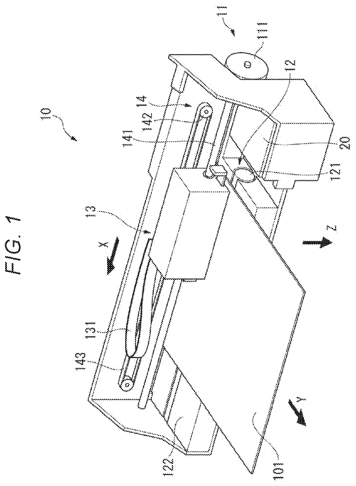
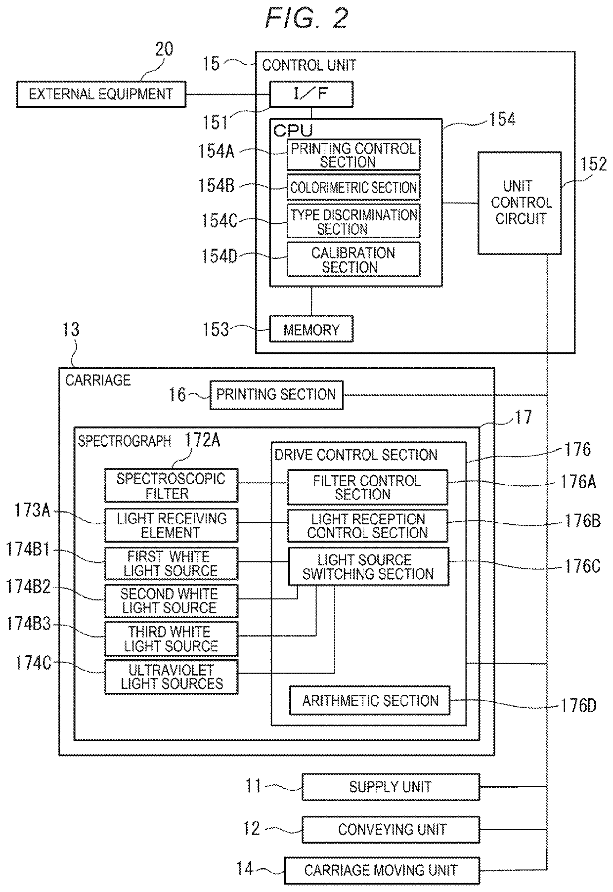
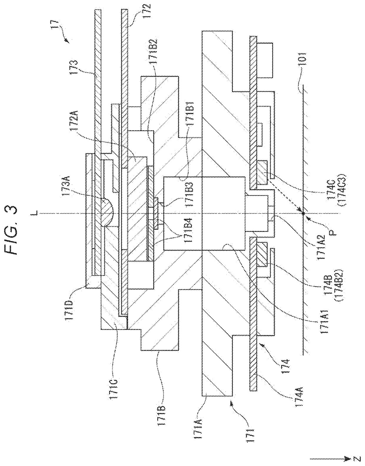
  • Measurement Device, Electronic Apparatus And Measurement Method
  • Measurement Device, Electronic Apparatus And Measurement Method
  • Measurement Device, Electronic Apparatus And Measurement Method

Examples


modified examples

[0135]It should be noted that the present disclosure is not limited to the embodiment described above, but includes modifications, improvements, and so on within a range where the advantages of the present disclosure can be achieved. Modified Example 1

[0136]In the embodiment described above, the spectral reflectivities are calculated by combining all of the partial spectral reflectivities with respect to the combinations a through d, but this is not a limitation.

[0137]For example, in the embodiment described above, there are included the combinations a through c each for putting on one of the three white light sources 174B, and putting off the other of the white light sources 174B and the ultraviolet light sources 174C, and the combination d for putting on all of the white light sources 174B and the ultraviolet light sources 174C.

[0138]In this case, it is also possible to calculate first spectral reflectivities Aj1 obtained by combining the partial spectral reflectivities correspond...

modified example 2

[0141]In the embodiment described above, there are illustrated such combinations a through d as shown in FIG. 5, but this is not a limitation. FIG. 12 is a diagram showing another example of the light source combinations.

[0142]In the example shown in FIG. 12, the combination e is a combination of putting the first white light source 174B1 and the first ultraviolet light source 174C1 on, and putting the other light sources off. The combination f is a combination of putting the second white light source 174B2 and the second ultraviolet light source 174C2 on, and putting the other light sources off. The combination g is a combination of putting the third white light source 174B3 and the third ultraviolet light source 174C3 on, and putting the other light sources off. The combination h is a combination of putting all of the three white light sources 174B on, and putting all of the three ultraviolet light sources 174C off.

[0143]According also to such combinations e through h, similarly t...

modified example 3

[0146]In the embodiment described above, there is described the example in which the three ultraviolet light sources 174C have the same emission spectrum, but it is also possible for the these ultraviolet light sources 174C to have respective emission spectrums different from each other. For example, it is also possible to adopt a configuration of including a first excitation light source for outputting first excitation light for emitting a first fluorescence color, a second excitation light source for outputting second excitation light for emitting a second fluorescence color, and a third excitation light source for outputting third excitation light for emitting a third fluorescence color.

[0147]In this case, it is also possible to further add, for example, a combination of making the three while light sources 174B and the first excitation light source emit light, a combination of making the three while light sources 174B and the second excitation light source emit light, and a comb...


PUM


Abstract

A measurement device includes a plurality of light sources configured to emit light toward a measurement object, and having a same emission spectrum, a spectroscopic measurement section configured to perform spectroscopic measurement on the light reflected by the measurement object, a light source switching section configured to switch a combination of the light sources to be put on or off out of the plurality of light sources, and an arithmetic section configured to calculate the spectral reflectivity of the measurement object based on a spectroscopic measurement result obtained by the spectroscopic measurement section when putting on or off the plurality of light sources with a plurality of the combinations.

Description

[0001]The present application is based on, and claims priority from, JP Application Serial Number 2018-122975, filed Jun. 28, 2018, the disclosure of which is hereby incorporated by reference herein in its entirety.BACKGROUND1. Technical Field[0002]The present disclosure relates to a measurement device, an electronic apparatus and a measurement method.2. Related Art[0003]In the past, there has been known a measurement device for performing spectroscopic measurement of a measurement object (see, e.g., JP-A-2013-107269 (Document 1)).[0004]The printing device described in Document 1 is provided with a print medium discriminator (a measurement device). The print medium discriminator irradiates the print medium with light from a single light source, makes the light reflected by the print medium pass through a spectroscope, and then receives light with a predetermined wavelength having passed through the spectroscope with an optical sensor. Then, the print medium discriminator calculates ...

Claims


Application Information

Patent Timeline
IPC IPC(8): G01N21/55G01J3/26G01J3/50G01J3/02
CPCG01N2021/555G01N21/55G01J3/501G01J3/26G01J3/027G01N21/01B41J11/009G01N2201/061G01N21/86G01N21/255G01N2201/0627G01N2021/6417G01J2003/104G01J3/10G01J2003/106
Inventor KASAHARA, HIDEAKI
Owner SEIKO EPSON CORP
Learn More