Wave plate, optical pickup and optical disc apparatus

a technology of which is applied in the field of wave plate, optical pickup and optical disc apparatus, can solve the problems of large manufacturing cost of optical pickup, difficult to further increase the output power of its laser light source, and wave plate thickness, etc., to achieve the effect of minimizing such a variation in read signal

Active Publication Date: 2010-09-16
PANASONIC CORP
View PDF11 Cites 0 Cited by
  • Summary
  • Abstract
  • Description
  • Claims
  • Application Information

AI Technical Summary

Benefits of technology

[0030]It is therefore an object of the present invention to provide a wave plate, an optical pickup and an optical ...

Problems solved by technology

The greater the number of members to assemble together, the larger the number of assembling process steps required and the bigger the manufacturing cost of the optical pickup.
As for light with the wavelength λ1 for use to scan a BD or a DVD, on the other hand, it is difficult to further increase the output power of its laser light source.
Those wave plates, however, are too...

Method used


Image

  • Wave plate, optical pickup and optical disc apparatus
  • Wave plate, optical pickup and optical disc apparatus
  • Wave plate, optical pickup and optical disc apparatus

Examples


Embodiment Construction

[0044]Hereinafter, preferred embodiments of a polarizer, an optical pickup and an optical disc apparatus according to the present invention will be described with reference to the accompanying drawings. In the following description, any pair of components shown in multiple drawings and having substantially the same function will be identified by the same reference numeral.

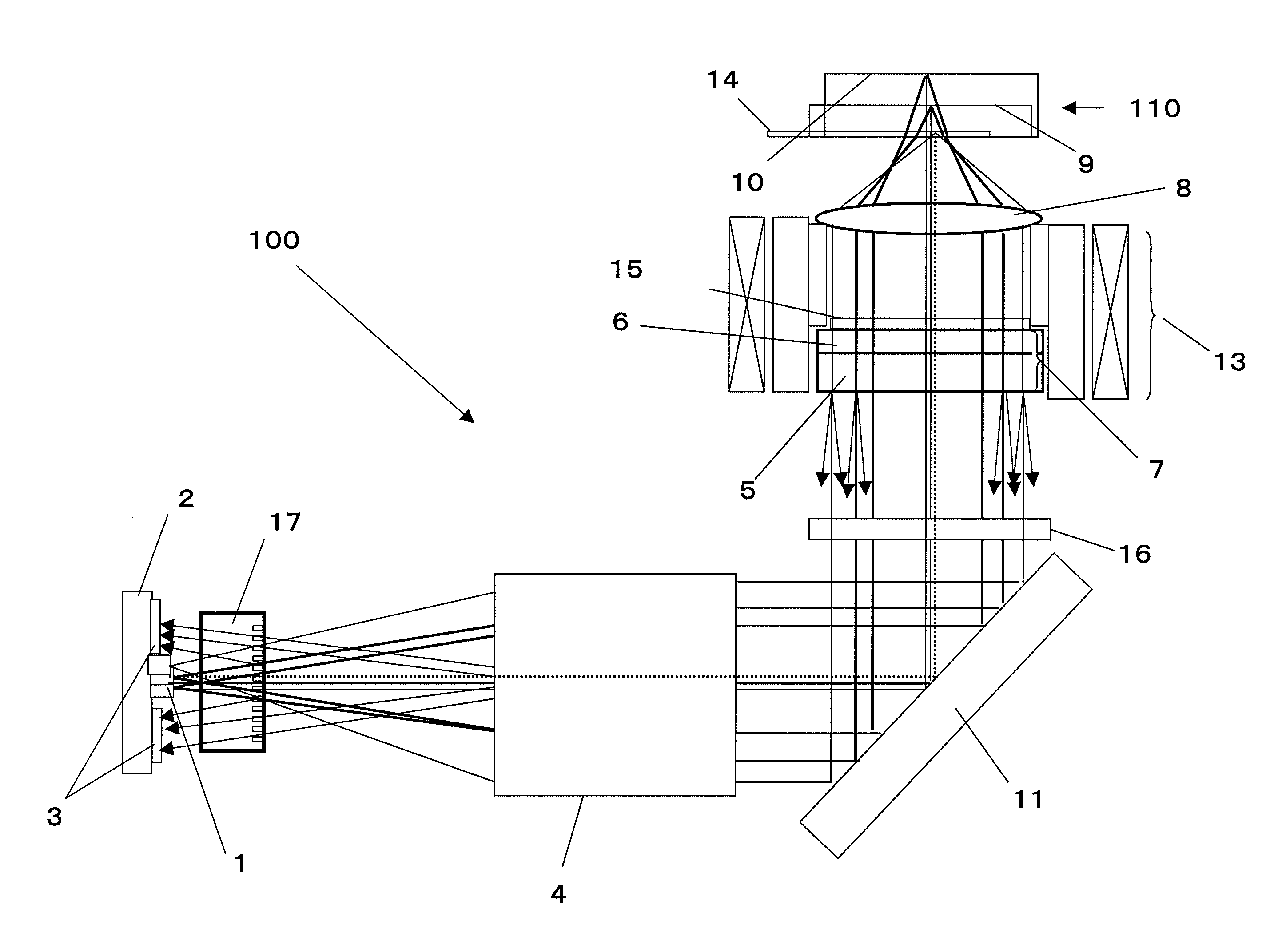
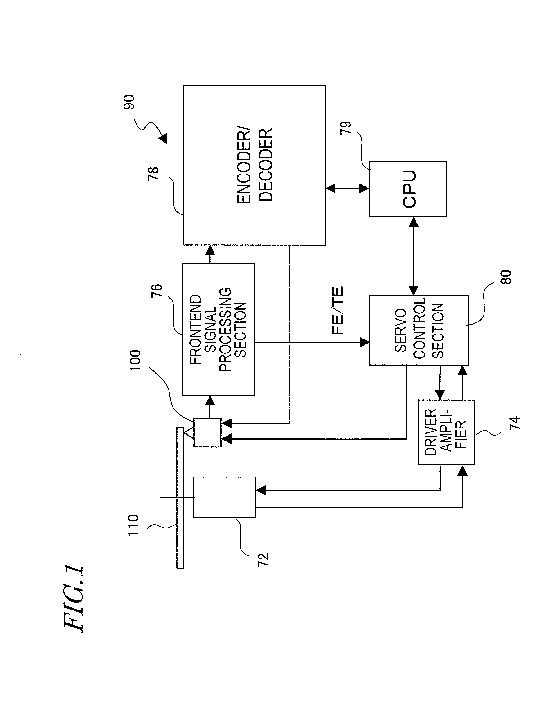
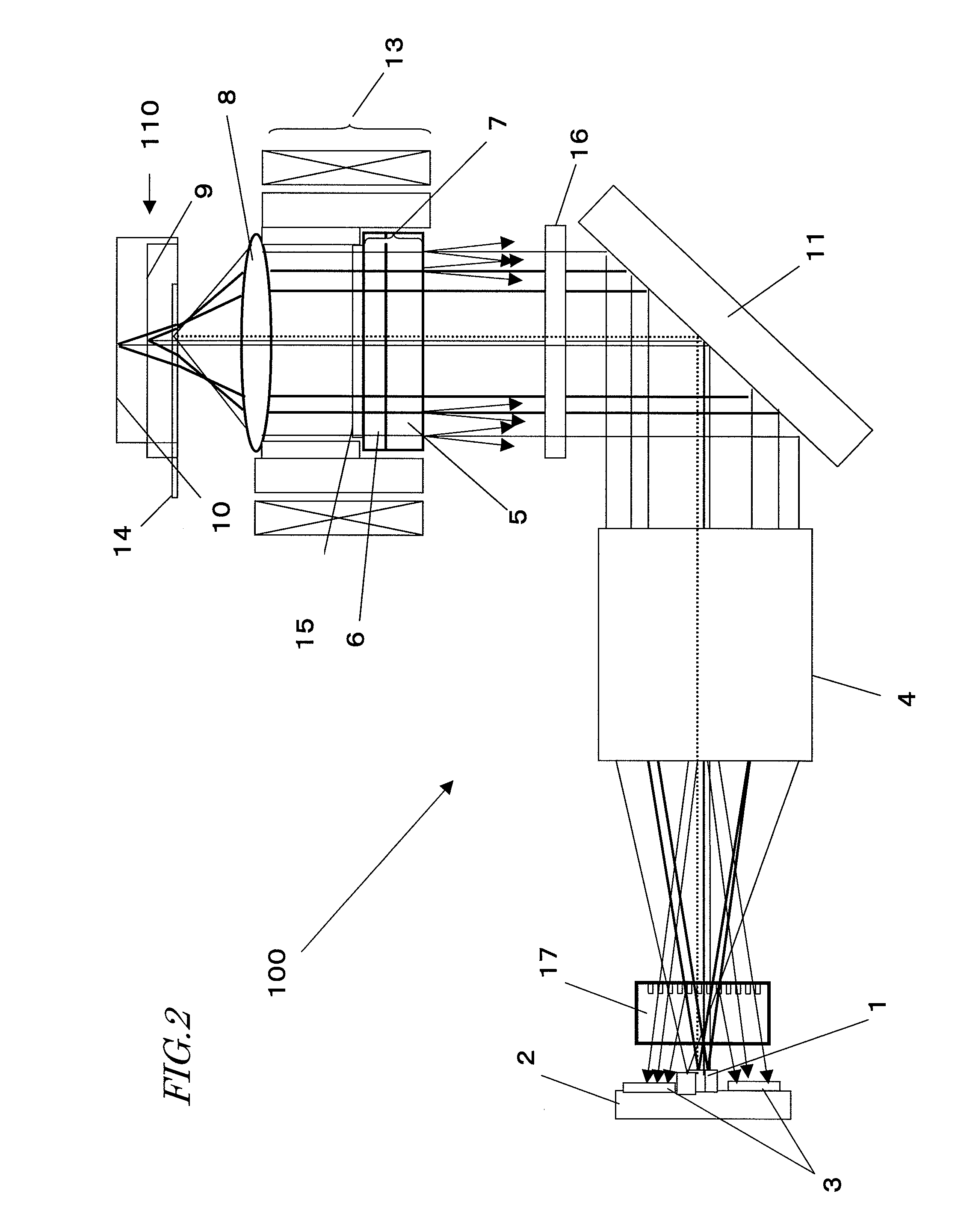
[0045]FIG. 1 schematically illustrates a configuration for an optical disc apparatus 90 as a preferred embodiment of the present invention. The optical disc apparatus 90 includes an optical pickup 100, a disc motor 72 to rotate an optical disc 110, a driver amplifier 74, a frontend signal processing section 76, an encoder / decoder 78, a CPU 79 and a servo control section 80.

[0046]The optical pickup 100 emits a laser beam with a predetermined wavelength toward the optical disc 110, receives its reflected light, and outputs an RF signal representing the intensity of the reflected light received. The RF signal is sent ...


PUM


Abstract

An optical pickup includes a wave plate on an optical path to be followed by every light beam emitted from three light sources (with wavelengths λ1, λ2 and λ3, respectively) both on their way toward an optical disc and back from the disc toward a photodetector. The wave plate has two layers with different retardations and different optic axis directions. The sum of the retardations of the first and second layers is defined to be approximately 5/4λ1, ¾λ2 and ½λ3 to the light beams with the wavelengths λ1, λ2 and λ3. Due to the difference in optic axis direction between the first and second layers, the linearly polarized light beams with the wavelengths λ1 and λ2 on their way toward the disc are transformed into circularly polarized light beams, which will be transformed again, on their way back from the disc, into linearly polarized light beams, of which the polarization direction is perpendicular to that of the light beams on their way toward the disc, thereby transmitting the light beam with the wavelength λ3 as a linearly polarized light beam both on its way toward, and back from, the disc.

Description

BACKGROUND OF THE INVENTION[0001]1. Field of the Invention[0002]The present invention relates to a wave plate for use to get polarization conversion done appropriately on three light beams with mutually different wavelengths. The present invention also relates to an optical pickup with a laser light source that can emit laser beams with mutually different wavelengths for use to read and / or write a signal from / on multiple different types of optical discs such as CDs, DVDs and Blu-ray Discs (which will be referred to herein as “BDs”) and an optical disc apparatus including such an optical pickup.[0003]2. Description of the Related Art[0004]Recently, in the field of optical information storage including optical disc technologies, various standards have been set up one after another and a variety of storage media, compliant with those standards, has become increasingly popular year by year. To keep up with those trends, appliances that can read and / or write information from / on those var...

Claims


Application Information

Patent Timeline
IPC IPC(8): G11B7/135G11B20/10
CPCG11B7/1275G11B2007/0006G11B7/1367
Inventor ASADA, JUN-ICHIMOMOO, KAZUO
Owner PANASONIC CORP
Why Eureka
Try Eureka