Imaging lens and imaging apparatus

a technology of imaging apparatus and lens, applied in the direction of optics, optical elements, instruments, etc., can solve the problems of large field curvature and large astigmatism fluctuation during focusing, and achieve the effect of suppressing astigmatism fluctuation, small field curvature, and favorable optical performan

Active Publication Date: 2020-01-02
FUJIFILM CORP
View PDF0 Cites 2 Cited by
  • Summary
  • Abstract
  • Description
  • Claims
  • Application Information

AI Technical Summary

Benefits of technology

[0020]According to the present invention, the lens system consists of, in order from the object side, a positive first lens group that moves to the object side during focusing from the distant object to the close-range object, and a second lens group that does not move during focusing. In the lens system, by appropriately setting specific configurations of the first lens group and the second lens group, predetermined conditional expressions are satisfied. With such a configuration, it is possible to provide an imaging lens, which has a small field curvature and has favorable optical performance by suppressing fluctuation in astigmatism during focusing, and an imaging apparatus comprising the imaging lens.

Problems solved by technology

However, the lens systems described in JP2013-178365A and JP2013-210604A each have a disadvantage that field curvature is large.
The lens system described in JP2013-231941A has a disadvantage that fluctuation in astigmatism during focusing is large.

Method used


Image

  • Imaging lens and imaging apparatus
  • Imaging lens and imaging apparatus
  • Imaging lens and imaging apparatus

Examples


example 1

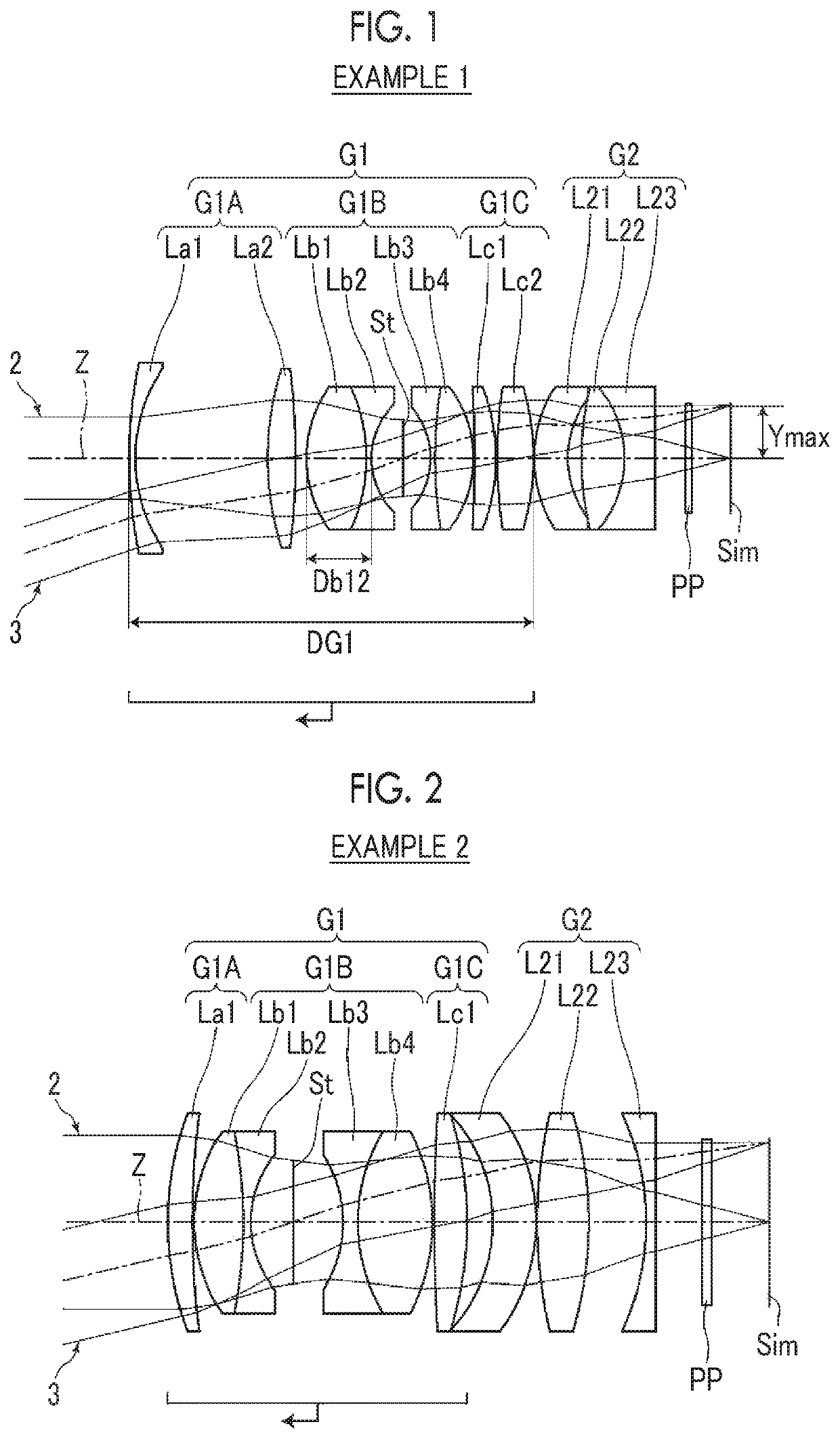
[0055]A lens configuration of an imaging lens of Example 1 is shown in FIG. 1, and a configuration and a method thereof shown in the drawing is as described above. Therefore, repeated description is partially omitted herein. The imaging lens of Example 1 consists of, in order from the object side, a first lens group G1 having a positive refractive power, and a second lens group G2 having a positive refractive power. During focusing from the object at infinity to the close-range object, the entire first lens group G1 integrally moves from the image side to the object side, and the second lens group G2 remains stationary with respect to the image plane Sim. The first lens group G1 consists of, in order from the object side, a first-A sub-lens group G1A having a positive refractive power, a first-B sub-lens group G1B, and a first-C sub-lens group G1C having a positive refractive power. The first-A sub-lens group G1A consists of two lenses La1 and La2 in order from the object side. The ...

example 2

[0061]FIG. 2 shows a lens configuration of the imaging lens of Example 2. The schematic configuration of the imaging lens of Example 2 is the same as that of Example 1 except that the first-A sub-lens group G1A consists of one lens La1 and the first-C sub-lens group G1C consists of one lens Lc1. Table 3 shows basic lens data of the imaging lens of Example 2, Table 4 shows specification and variable surface distances, and FIG. 8 shows aberration diagrams thereof.

TABLE 3Example 2SurfaceNumberRDNdvd 134.684092.6591.8348142.72 296.726610.200 318.603185.1831.6180063.33 4-53.111400.8101.5407247.23 512.036654.547 6(St)∞5.353 7-14.250881.6201.6129337.00 819.927898.0001.6180063.33 9-22.476440.20010203.350673.5111.8348142.7211-41.27145DD[11]12-17.819034.6621.8466623.7813-20.440610.1001452.537685.5701.6180063.3315-42.346456.07016-30.223281.0001.7552027.51172525252.525255.00018∞1.0001.5163364.1419∞6.231

TABLE 4Example 2Infinity0.2 mf36.019—fnear—37.710FNo.1.882.242ω(°)28.824.4DD[11]2.79013.268

example 3

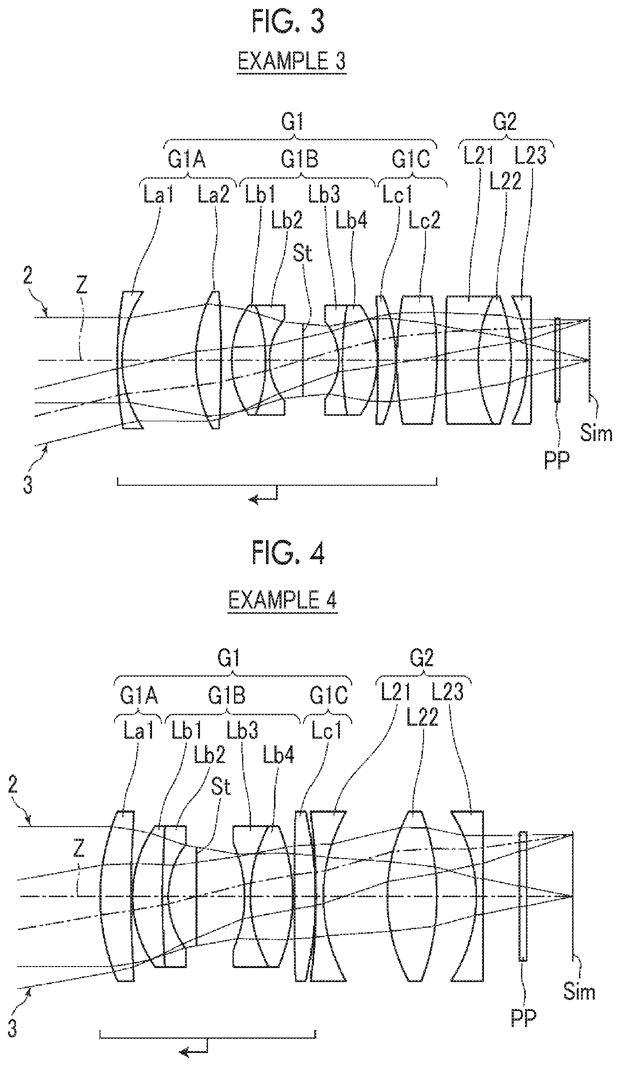
[0062]FIG. 3 shows a lens configuration of the imaging lens of Example 3. The schematic configuration of the imaging lens of Example 3 is the same as that of Example 1 except that the second lens group G2 has a negative refractive power. Table 5 shows basic lens data of the imaging lens of Example 3, Table 6 shows specification and variable surface distances, and FIG. 9 shows aberration diagrams thereof.

TABLE 5Example 3SurfaceNumberRDNdvd 190.392281.0001.6727032.10 227.1143715.722 333.685425.4011.8000029.84 4-232.997342.194 521.309137.2601.6180063.33 6-34.565350.8001.6200436.26 714.039597.142 8(St)∞7.481 9-13.833870.8001.6398034.471072.487897.3981.6180063.3311-21.802720.20012-264.076263.7621.6516058.5513-37.166190.2001476.833078.5521.6516058.5515-85.69829DD[15]16267.066577.0101.5168064.201732.625107.0001.6180063.3318-41.278573.36419-32.590031.0001.9108235.2520-426.721085.00021∞1.0001.5163364.1422∞6.295

TABLE 6Example 3Infinity0.2 mf34.489—fnear—33.716FNo.1.852.112ω(°)30.027.8DD[15]1....


PUM


Abstract

The imaging lens consists of, in order from the object side, a positive first lens group that moves to the object side during focusing from a long distance to a short distance, and a second lens group that does not move during focusing. The first lens group has a first-B sub-lens group. The first-B sub-lens group consists of, in order from the object side, a positive b1 lens, a negative b2 lens concave toward the image side, an aperture stop, a negative b3 lens concave toward the object side, and a positive b4 lens. The second lens group consists of, in order from the object side, a negative lens, a positive lens, and a negative lens. Predetermined conditional expressions are satisfied.

Description

CROSS REFERENCE TO RELATED APPLICATIONS[0001]The present application is a Continuation of PCT International Application No. PCT / JP2018 / 008425 filed on Mar. 5, 2018, which claims priority under 35 U.S.C. § 119(a) to Japanese Patent Application No. 2017-049840 filed on Mar. 15, 2017. Each of the above applications is hereby expressly incorporated by reference in its entirety, into the present application.BACKGROUND OF THE INVENTION1. Field of the Invention[0002]The present invention relates to an imaging lens and an imaging apparatus. In particular, the present invention relates to an imaging lens, which is suitable for a factory automation (FA) camera, a machine vision (MV) camera, a digital camera, a surveillance camera, an on-board camera, and the like, and an imaging apparatus comprising the imaging lens.2. Description of the Related Art[0003]Examples of the imaging lens having a focusing function conventionally known include imaging lenses described in JP2013-178365A, JP2013-2106...

Claims


Application Information

Patent Timeline
Patent Type & Authority Applications(United States)
IPC IPC(8): G02B9/10G02B13/02
CPCG02B13/02G02B13/18G02B9/10G02B13/24G02B9/64
Inventor OKADA, KAZUYOSHI
Owner FUJIFILM CORP
Why Eureka
Try Eureka