Pneumatic Tire

Pending Publication Date: 2020-01-09
YOKOHAMA RUBBER CO LTD
View PDF0 Cites 0 Cited by
  • Summary
  • Abstract
  • Description
  • Claims
  • Application Information

AI Technical Summary

Benefits of technology

[0003]The present technology provides a pneumatic tire that is suitable as a tire for

Problems solved by technology

However, even with such a tire, driving performance on unpaved roads (in particular, traction characteristi

Method used


Image

  • Pneumatic Tire
  • Pneumatic Tire
  • Pneumatic Tire

Examples


Example

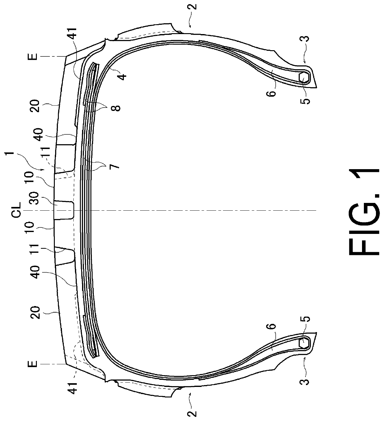
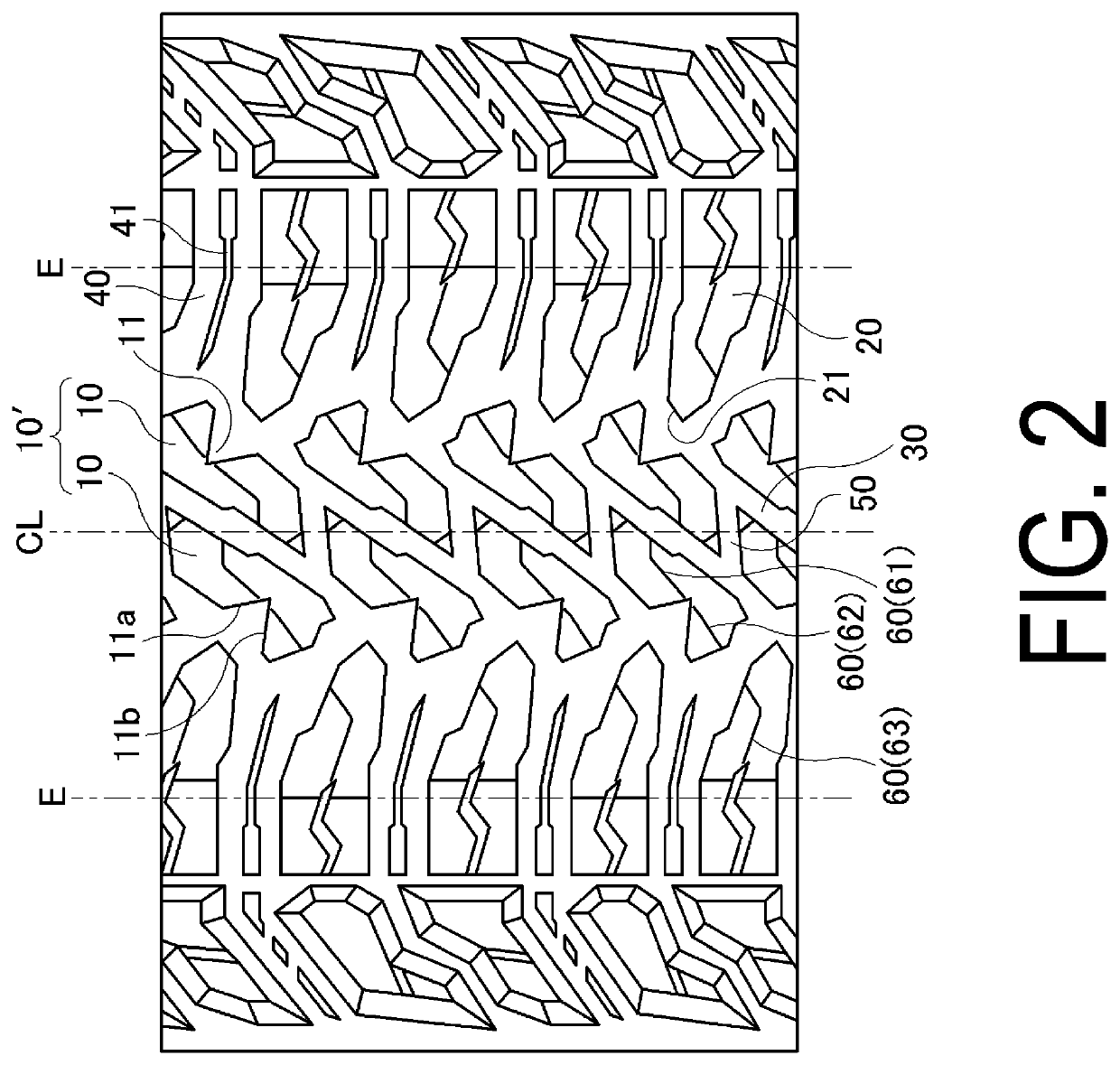
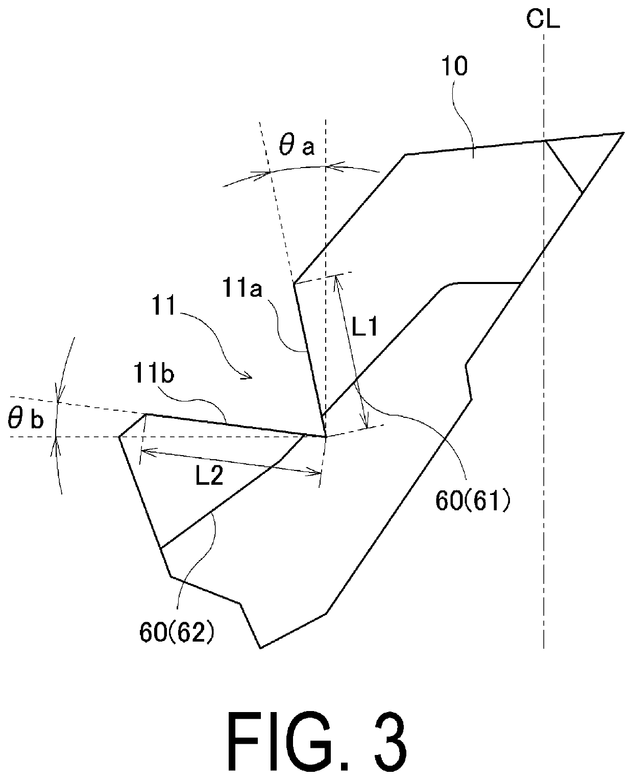
[0039]Seventeen types of pneumatic tires of Conventional Example 1, Comparative Examples 1 to 3, and Examples 1 to 13 are manufactured. The tire size of each of the tires is LT265 / 70R17, and the tire has a basic structure illustrated as an example in FIG. 1 and a tread pattern illustrated in FIG. 2 as a base pattern. The angle θa of the first wall with respect to the tire circumferential direction, the angle θb of the second wall with respect to the tire lateral direction, the angle of the third wall with respect to the straight line connecting the end point of the first wall, which is located adjacent to the shoulder block side and the end point of the second wall, which is located adjacent to the shoulder block, a ratio L3 / D1 of the length L3 of the third wall to the distance D1 between the end point of the first wall, which is located adjacent to the shoulder block and the end point of the second wall, which is located adjacent to the shoulder block, a positional relationship bet...


PUM


Abstract

In a pneumatic tire, center blocks in a center region of a tread portion form a pair sandwiching an inclined groove that extends inclined with respect to a circumferential direction. Each of the center blocks extends across an equator and includes a notch formed of first and second walls that are connected in a V-shape in a tread road contact surface. The first wall extends within +/−20° with respect to the circumferential direction, and the second wall extends within +/−10° with respect to a lateral direction. Each of shoulder blocks provided in a center region of the tread portion includes a third wall opposed to the notch and at an angle within +/−5° with respect to a straight line connecting an end point of the first wall, located adjacent to the shoulder block and an end point of the second wall, located adjacent to the shoulder block.

Description

TECHNICAL FIELD[0001]The present technology relates to a pneumatic tire suitable as a tire for driving on unpaved roads and, in particular, to a pneumatic tire that can provide improved driving performance on unpaved roads.BACKGROUND ART[0002]Pneumatic tires used for driving on unpaved roads such as an irregular ground, a mud land, a snowy road, a sand area, and a rocky area are provided with a tread pattern mainly including lug grooves or blocks that have many edge components, and the tread pattern having grooves, the area of which is large is generally employed. Such a tire obtains traction characteristics by engagement with mud, snow, sand, stones, rocks, or the like on a road surface (hereinafter, referred to collectively as “mud or the like”) and prevents the grooves from being clogged with mud or the like, and thus driving performance on unpaved roads is improved (for example, see Japan Unexamined Patent Publication No. 2015-223884). However, even with such a tire, driving per...

Claims


Application Information

Patent Timeline
IPC IPC(8): B60C11/11B60C11/12
CPCB60C2200/14B60C11/11B60C11/1204B60C11/1236B60C2011/0381B60C2011/1209
Inventor SUZUKI, YUHEI
Owner YOKOHAMA RUBBER CO LTD
Why Eureka
Try Eureka