
Coordinated driving type multi degree-of-freedom ultrasonic motor based on spherical hinge structure and working method of motor

A technology of ultrasonic motor and degree of freedom, applied in the direction of piezoelectric effect/electrostriction or magnetostriction motor, generator/motor, electrical components, etc., can solve the problem of no pre-pressure application method, etc., to solve the problem of pre-pressure Difficult to adjust, large thrust-to-weight ratio, and quick response

Inactive Publication Date: 2015-04-29
NANJING UNIV OF AERONAUTICS & ASTRONAUTICS
View PDF7 Cites 1 Cited by
  • Summary
  • Abstract
  • Description
  • Claims
  • Application Information

AI Technical Summary

Problems solved by technology

Proper preload is crucial to generate proper friction, without proper preload, the output torque of the motor may be zero
In ordinary single-degree-of-freedom ultrasonic motors, a suitable preloading scheme has been established, but for multi-degree-of-freedom ultrasonic motors with spherical rotors, there has been no suitable preloading method, which is generally carried out under laboratory conditions

Method used


Image

  • Coordinated driving type multi degree-of-freedom ultrasonic motor based on spherical hinge structure and working method of motor
  • Coordinated driving type multi degree-of-freedom ultrasonic motor based on spherical hinge structure and working method of motor
  • Coordinated driving type multi degree-of-freedom ultrasonic motor based on spherical hinge structure and working method of motor

Examples


Embodiment Construction

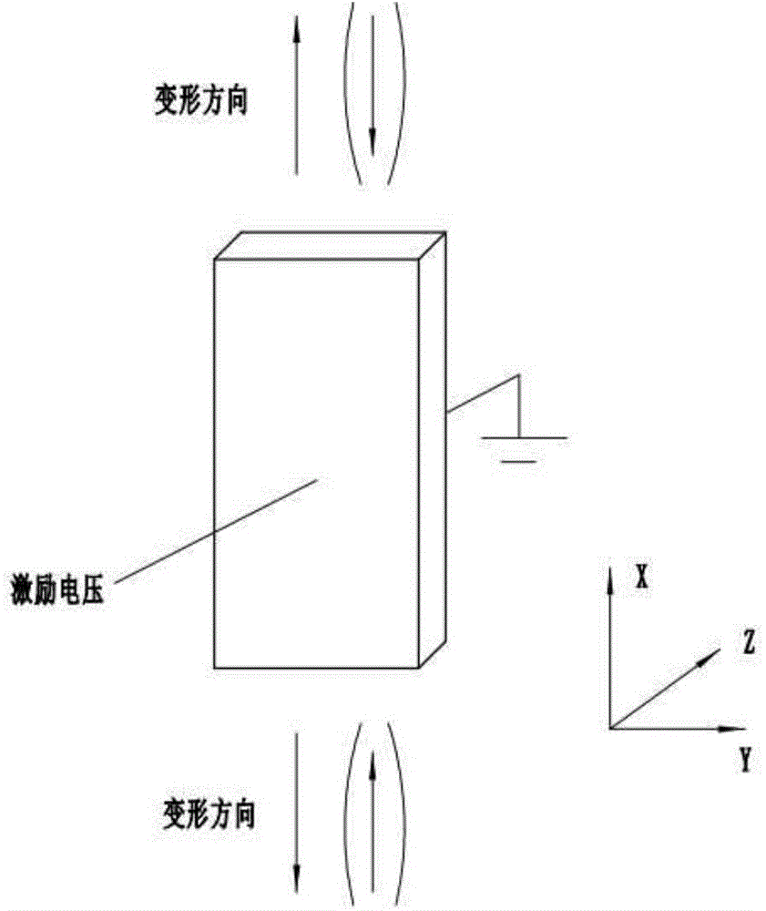
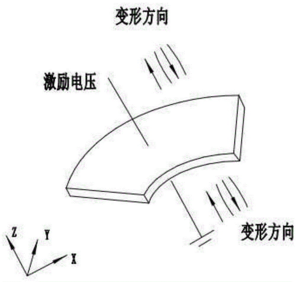
[0028] The inverse piezoelectric effect of piezoelectric ceramics refers to the phenomenon of mechanical deformation caused by applying an electric field to piezoelectric ceramics. According to different polarization modes of piezoelectric ceramics, the corresponding ways of inducing deformation are also different, and the present invention is based on the spherical hinge structure. The coordinated driving multi-degree-of-freedom ultrasonic motor utilizes the d31 effect of square piezoelectric ceramics and the d33 effect of ring piezoelectric ceramics. Let the directions corresponding to the x, y, and z coordinate axes be 1, 2, and 3, respectively. The d31 effect means that the electric field is applied along the polarization direction 3, and the induced strain is along the 1 direction, as shown in Fig. 1(a). The excitation voltage is applied later, and the mechanical deformation of elongation (shortening) is generated on the upper and lower sides; the d33 effect refers to the ...


PUM


Abstract

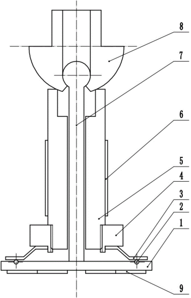
The invention discloses a coordinated driving type multi degree-of-freedom ultrasonic motor based on a spherical hinge structure. The motor comprises a bottom plate, balls, a disc spring, a pre-pressure adjusting slide block, a stator pedestal, square piezoelectric ceramic pieces, a connecting shaft, a spherical rotor and circular piezoelectric ceramic pieces, wherein a threaded hole is formed in the middle position of the bottom plate, four circular piezoelectric ceramic pieces are attached to the lower end face of the bottom plate and four semispherical holes are formed in the upper end face of the bottom plate, four balls are correspondingly placed on the four semispherical holes, the lower end face of the disc spring presses the balls while the upper end face of the disc spring is pressed by the pre-pressure adjusting slide block, the pre-pressure adjusting slide block is in threaded connection with the stator pedestal, the stator pedestal is of a structure with an external cuboid and an internal circular hole, the square piezoelectric ceramic pieces are adhered to the outer side faces of the stator pedestal, the spherical rotor is arranged above the stator pedestal, the upper tail end of the connecting shaft is of a spherical hinge structure, the connecting shaft is arranged at the lower tail end behind the circular hole in a threaded manner and is in threaded connection with the base, and the upper tail end of the connecting shaft is connected with the spherical rotor through the spherical hinge structure.

Description

Technical field: [0001] The invention relates to a coordinated-driven multi-degree-of-freedom ultrasonic motor based on a spherical joint structure and a working method thereof, belonging to the field of ultrasonic motors. Background technique: [0002] Ultrasonic motor is a new type of power output device that utilizes the inverse piezoelectric effect of piezoelectric ceramics and ultrasonic vibration. The coordinated drive multi-degree-of-freedom ultrasonic motor based on the spherical joint structure is a kind of multi-degree-of-freedom ultrasonic motor. [0003] For multi-degree-of-freedom ultrasonic motors, it can provide motion with two or more degrees of freedom, and has the advantages of small size, light weight, compact structure, fast response, low noise, and no electromagnetic interference. Therefore, it has a wide range of applications, such as the joints of micro-robots, endoscopes in industrial or medical fields, scanning devices for micro-cameras, and so on. ...

Claims


Application Information

Patent Timeline
IPC IPC(8): H02N2/10H02N2/12H02N2/14
Inventor 陈超杨明鹏陈海鹏石明友刘通
Owner NANJING UNIV OF AERONAUTICS & ASTRONAUTICS
Learn More