Novel H bridge driving circuit

A bridge drive circuit, a new type of technology, applied in the field of circuits, can solve the problems of drive circuit damage, easy impact power supply, etc., and achieve the effects of prolonging service life, improving safety, and reducing on-resistance

Pending Publication Date: 2017-07-21
SHANGHAI ORIENT CHIP TECH CO LTD
View PDF7 Cites 1 Cited by
  • Summary
  • Abstract
  • Description
  • Claims
  • Application Information

AI Technical Summary

Problems solved by technology

[0006] It is worth mentioning that there are two shortcomings in the traditional H-bridge drive circuit. One is that most of the traditional H-bridge drive circuits use PMOS transistors, such as figure 1 Q1 and Q2 are used as pull-up tubes, and the carriers of the PMOS tube are holes, and the carriers of the NMOS tube are free electrons, and the mobility of electrons is about 3 times that of holes.

Method used


Image

  • Novel H bridge driving circuit
  • Novel H bridge driving circuit
  • Novel H bridge driving circuit

Examples


Example Embodiment

[0024] The following describes in detail the embodiments of the present invention, examples of which are illustrated in the accompanying drawings, wherein the same or similar reference numerals refer to the same or similar elements or elements having the same or similar functions throughout. The embodiments described below with reference to the accompanying drawings are exemplary and are only used to explain the present invention, but not to be construed as a limitation of the present invention.

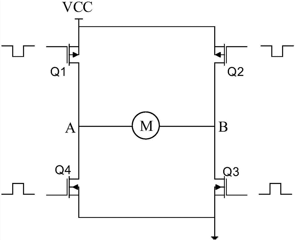
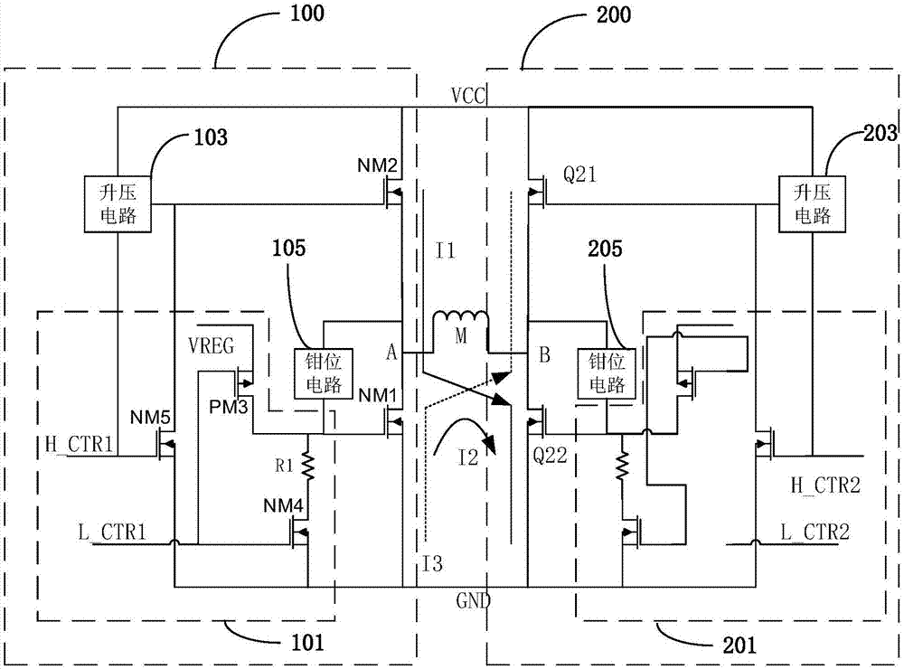
[0025] see Figure 1-Figure 3 , figure 2 A schematic diagram of a module structure of a novel H-bridge drive circuit provided in an embodiment of the present invention, the novel H-bridge drive circuit includes a first drive module 100 and a second drive module 200, wherein the first drive module 100 and the second drive The module 200 constitutes the half-bridge circuit of the novel H-bridge drive circuit.

[0026] In some embodiments, the second driving module 200 and the first ...


PUM


Abstract

The invention provides a novel H bridge driving circuit. The novel H bridge driving circuit comprises a power source end VCC, a grounding end GND, a first driving module and a second driving module, wherein the first driving module comprises a transistor NM1, a clamp circuit, a transistor NM2, a boost circuit and a control circuit, the transistor NM2 and the transistor NM1 are sequentially connected in series between the power source end VCC and the grounding end GND, the transistor NM2 is an NMOS tube, the boost circuit, the transistor NM1, the transistor NM2 and the clamp circuit are connected with the control circuit, the boost circuit is connected with the power source end VCC and the transistor NM2, and the clamp circuit is connected with the transistor NM1. The novel H bridge driving circuit is advantaged in that a pull-up tube of a traditional H bridge driving circuit is replaced by the NMOS tube from a PMOS tube, and conduction resistance of the whole H bridge driving circuit is reduced.

Description

technical field [0001] The invention relates to the field of circuits, in particular, the invention relates to a novel H-bridge drive circuit. Background technique [0002] H-bridge is a typical DC motor control circuit, because its circuit shape resembles the letter H, so it is named "H-bridge", such as figure 1 Shown is a conventional H-bridge circuit, it is worth noting that, figure 1 It is just a schematic diagram, not a complete circuit diagram. [0003] The circuit of the traditional H-bridge includes 4 vertical legs, wherein Q1 and Q3 form a group, and Q2 and Q4 form a group. The specific working principle is as follows: [0004] When Q1 and Q3 are turned on, the load current flows out from the power supply VCC and flows through A to B. At this time, point A of the load terminal is at a positive potential relative to point B, and the motor rotates forward; [0005] When the motor rotates at a certain angle, in order to ensure that the direction of the motor remain...

Claims


Application Information

Patent Timeline
IPC IPC(8): H02P7/03
CPCY02B70/10
Inventor 不公告发明人
Owner SHANGHAI ORIENT CHIP TECH CO LTD
Why Eureka
Try Eureka