
Trench mosfet with resurf stepped oxide and diffused drift region

a technology of mosfet and drift region, which is applied in the field of cell structure, device configuration and fabrication process of semiconductor power devices, can solve the problems of difficult to control the various gradient doping profiles in the manufacturing process, and not cost effective for mass production, so as to achieve better cost effectiveness and easy control

Active Publication Date: 2013-07-04
FORCE MOS TECH CO LTD
View PDF0 Cites 63 Cited by
  • Summary
  • Abstract
  • Description
  • Claims
  • Application Information

AI Technical Summary

Benefits of technology

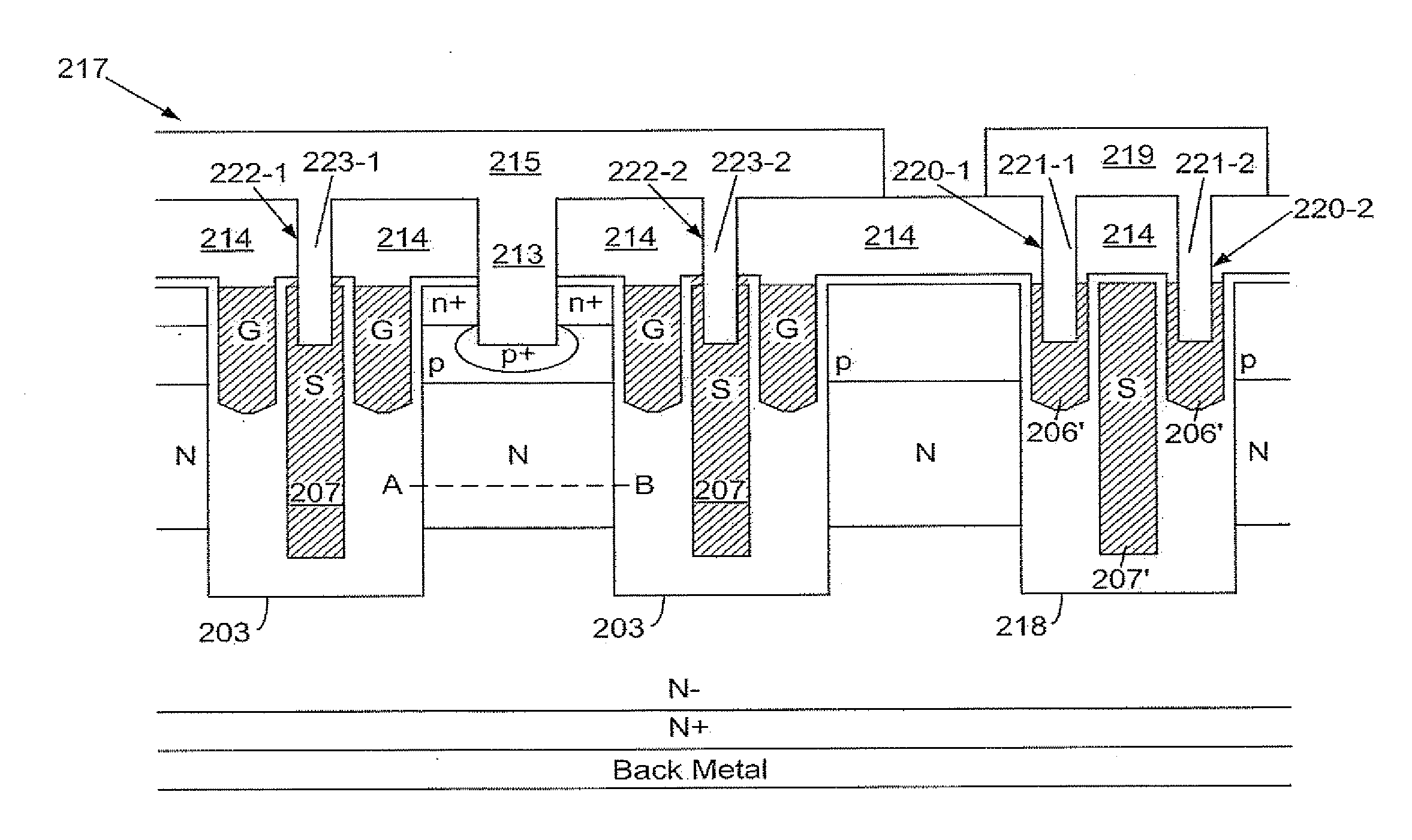
The present invention provides a method for reducing on-resistance in a semiconductor device by using an angle ion implantation and a diffusion step, which results in a diffused drift region with higher doping concentration than the epitaxial layer. This method is cost-effective and easier to control the doping concentration. Additionally, the diffused drift region has higher doping concentration near the trench sidewalls of the gate trenches than in the center of the mesa.

Problems solved by technology

That is to say, an additional mask for definition of the location of the split gate electrodes is required in the prior art, which is not cost effective for mass production.
As shown in FIG. 1C, multiple epitaxial layers with different gradient doping profiles are required, which is also not cost effective for mass production.
Moreover, it is difficult to control the various gradient doping profiles in the manufacturing process.

Method used


Image

  • Trench mosfet with resurf stepped oxide and diffused drift region
  • Trench mosfet with resurf stepped oxide and diffused drift region
  • Trench mosfet with resurf stepped oxide and diffused drift region

Examples


Embodiment Construction

[0026]In the following Detailed Description, reference is made to the accompanying drawings, which forms a part thereof, and in which is shown by way of illustration specific embodiments in which the invention may be practiced. In this regard, directional terminology, such as “top”, “bottom”, “front”, “back”, etc., is used with reference to the orientation of the Figure(s) being described. Because components of embodiments can be positioned in a number of different orientations, the directional terminology is used for purpose of illustration and is in no way limiting. It is to be understood that other embodiments may be utilized and structural or logical changes may be make without departing from the scope of the present invention. The following detailed description, therefore, is not to be taken in a limiting sense, and the scope of the present invention is defined by the appended claims. It is to be understood that the features of the various exemplary embodiments described herein...


PUM


Abstract

A trench MOSFET with split gates and diffused drift region for on-resistance reduction is disclosed. Each of the split gates is symmetrically disposed in the middle of the source electrode and adjacent trench sidewall of a deep trench. The inventive structure can save a mask for definition of the location of the split gate electrodes. Furthermore, the fabrication method can be implemented more reliably with lower cost.

Description

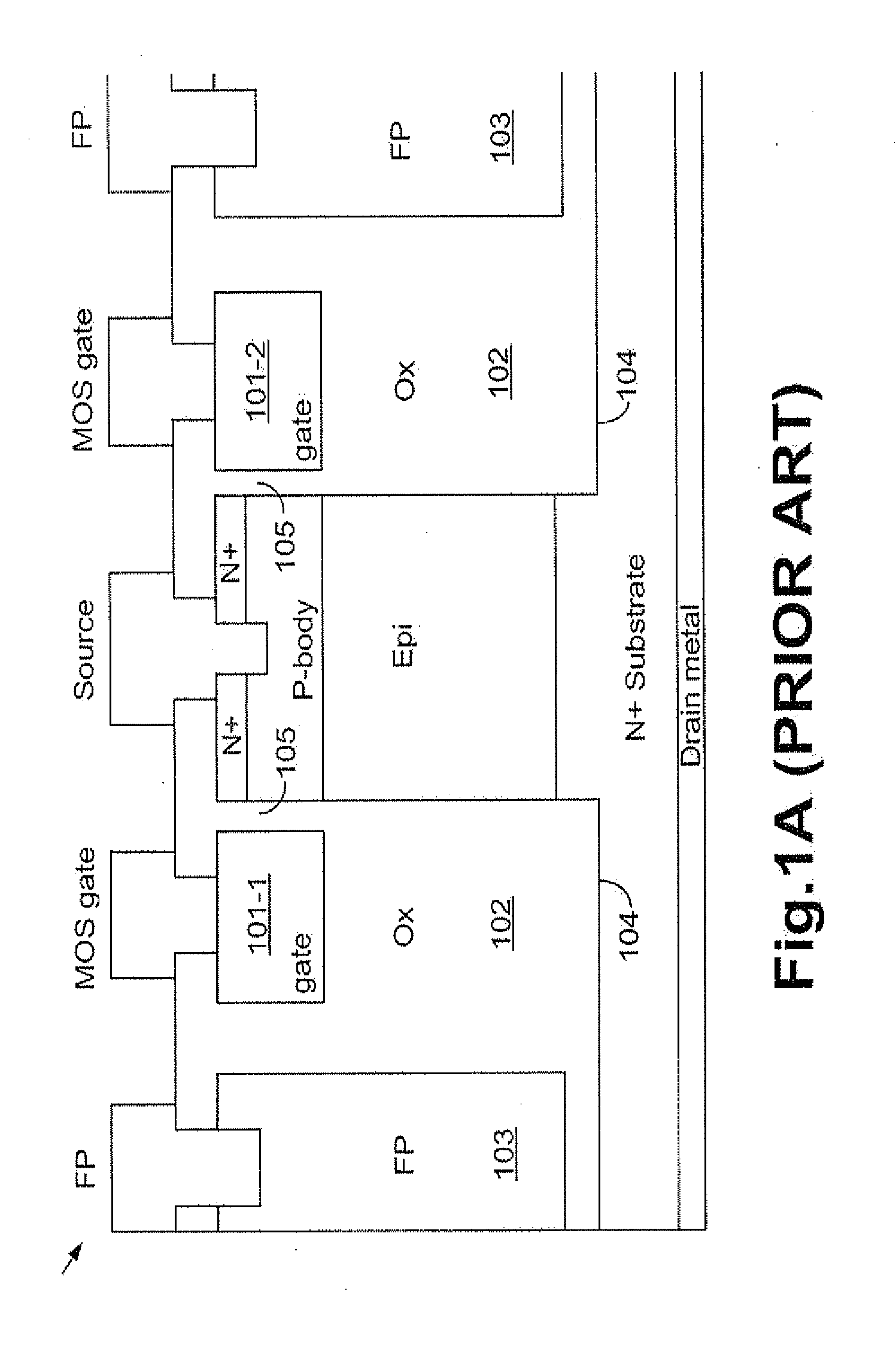
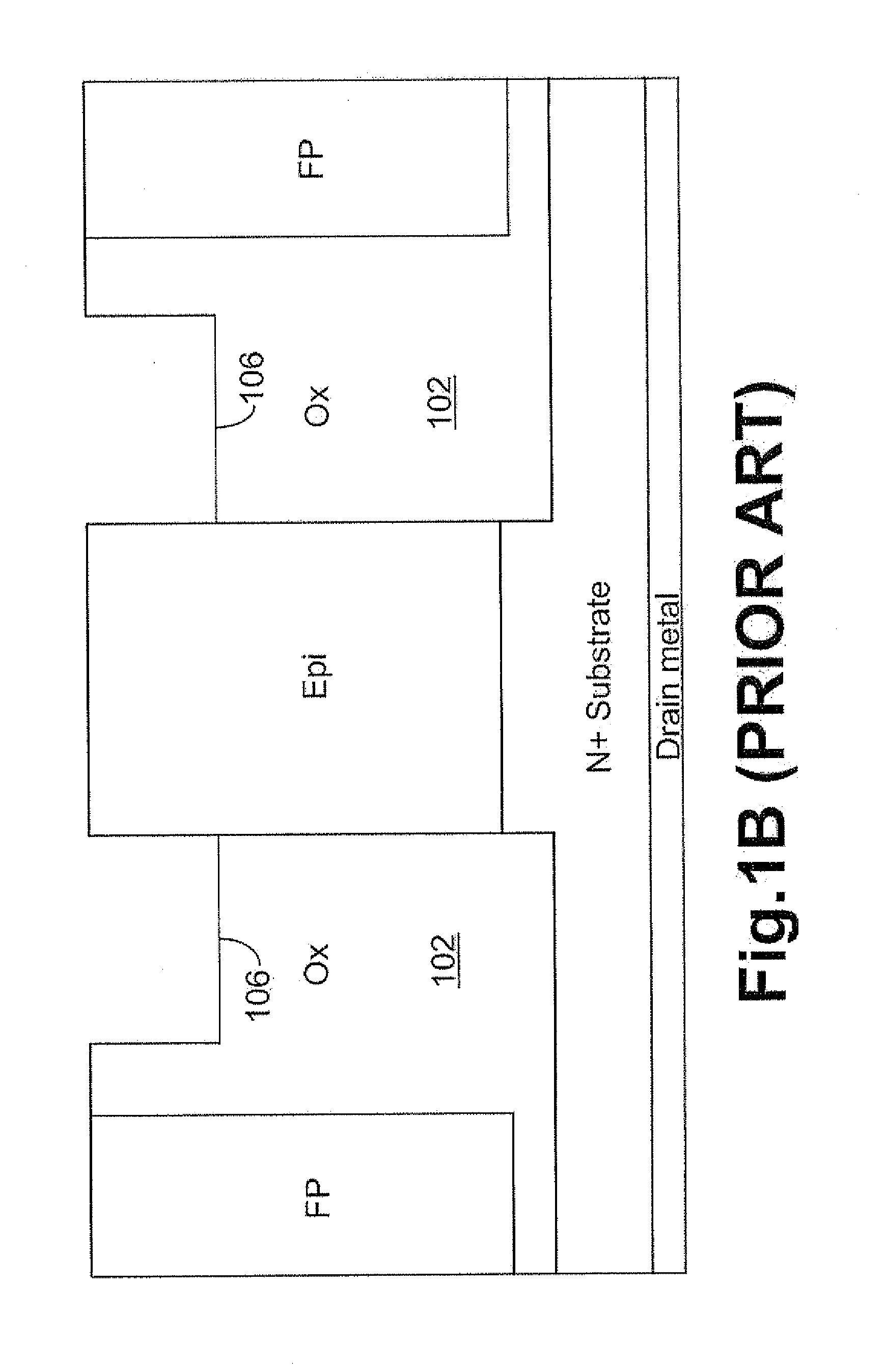
FIELD OF THE INVENTION[0001]This invention relates generally to the cell structure, device configuration and fabrication process of semiconductor power devices. More particularly, this invention relates to a novel and improved cell structure, device configuration and improved fabrication process of a trench MOSFET (Metal Oxide Semiconductor Field Effect Transistor).BACKGROUND OF THE INVENTION[0002]Please refer to FIG. 1A for a trench MOSFET 100 disclosed in a prior art of U.S. Pat. No. 7,829,944 and U.S. Pat. No. 7,791,132 having split gate electrodes (101-1 and 101-2), wherein each of the split gate electrodes (101-1 and 101-2) is asymmetrically disposed in a thick insulation layer 102 between a field plate 103 and trench sidewalls of a deep trench 104, and isolated from the trench sidewall of the deep trench 104 by a gate oxide 105. FIG. 1B shows manufacturing process for forming the split gate electrodes (101-1 and 101-2) of the trench MOSFET 100 of FIG. 1A according to the same ...

Claims


Application Information

Patent Timeline
IPC IPC(8): H01L29/78H01L21/336
CPCH01L21/26586H01L29/407H01L29/41766H01L29/4236H01L29/42368H01L29/42372H01L29/0878H01L29/456H01L29/66727H01L29/66734H01L29/7811H01L29/7813H01L29/0619H01L29/42376
Inventor HSIEH, FU-YUAN
Owner FORCE MOS TECH CO LTD
Learn More