Unlock instant, AI-driven research and patent intelligence for your innovation.

Rotation indicator device

Pending Publication Date: 2020-01-16
BUSINESS LINES
View PDF0 Cites 1 Cited by
  • Summary
  • Abstract
  • Description
  • Claims
  • Application Information

AI Technical Summary

Benefits of technology

The invention is a device that can be attached to a polygonal fastener like a wheel nut. The device includes a body with a hole and two tapered regions made of flexible material that surround the hole. These regions can be compressed to securely attach the device to the fastener and prevent it from spinning. This design helps prevent damage to the device and maintains a strong grip on the wheel nut.

Problems solved by technology

This arrangement may inhibit undesirable deformation of the device and / or twisting of the body.

Method used


Image

  • Rotation indicator device
  • Rotation indicator device

Examples


Embodiment Construction

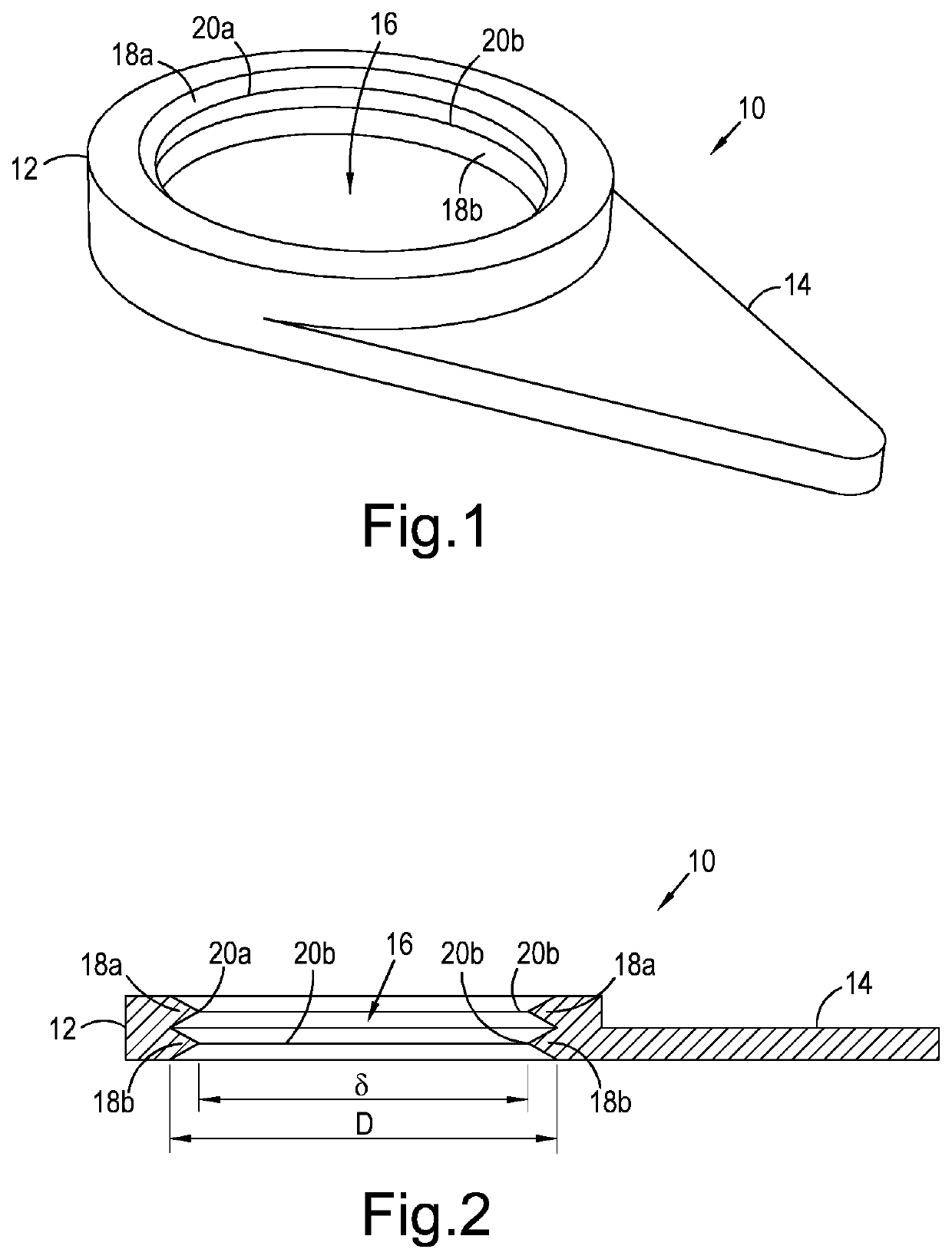
[0014]FIG. 1 shows a rotation indicator device 10 according to an embodiment of the invention. The device 10 has particular application as a safety device for releasable attachment to a wheel nut 40 (see FIG. 4) to indicate a rotation thereof. As shown in the accompanying figures, the device 10 may have a substantially annular body 12 and a triangular pointer 14 extending laterally from a side of the body 12. In use, the pointer 14 facilitates indication of the rotation of the wheel nut 40. The body 12 has an annular bore 16 formed to extend axially through its centre, the bore 16 having a nominal diameter D. The bore 16 is configured to allow the body 12 to be mounted onto the wheel nut 40. Specifically, the bore 16 is configured to allow the body 12 to be mounted onto the wheel nut 40 in any angular orientation relative thereto. This is possible owing to a pair of tapered regions 18a, 18b extending circumferentially around a periphery of the bore 16, i.e. extending from the body 1...


PUM

PropertyMeasurementUnit
Diameteraaaaaaaaaa
Diameteraaaaaaaaaa
Diameteraaaaaaaaaa

Abstract

There is provided a rotation indicator device for mounting onto a polygonal fastener, such as a wheel nut. The device comprises a body having a bore. A pair of tapered regions, which are formed of a resilient material, extend around a periphery the bore, each of the regions being resiliently deformable to, in use, securely and releasably mount the body onto the polygonal fastener such that a rotation of the device relative to the polygonal fastener is inhibited. The device may be used as a safety device to indicate the rotation, i.e. loosening, of the polygonal fastener.

Description

TECHNICAL FIELD[0001]The invention relates to a rotation indicator device. The invention particularly, though not necessarily, relates to a rotation indicator device for mounting onto a polygonal fastener, e.g. a wheel nut, or other component having a multi-angular peripheral surface.BACKGROUND[0002]Various types of rotation indicator devices are known and such devices are widely used on heavy goods vehicles as a safety device to indicate the occurrence of loosening of individual wheel nuts. Many examples of known devices are described in earlier patent specifications, e.g. GB2458644 describes a rotation indicator device comprising an annular body formed of an elastomeric material. The body has a bore extending therethrough, the bore having an edge margin that is tapered in cross section such that the body is mountable onto a wheel nut in a manner that inhibits a relative rotation of the device and the wheel nut. This is possible because the edge margin is resiliently deformable to ...

Claims


Application Information

Patent Timeline
IPC IPC(8): B60B3/16F16B37/14
CPCB60B3/16B60B2900/3316F16B37/14B60B2360/50B60B3/165B60B5/02F16B2200/95F16B31/02
Inventor MARCZYNSKI, MICHAEL
Owner BUSINESS LINES
Features
  • R&D
  • Intellectual Property
  • Life Sciences
  • Materials
  • Tech Scout
  • Unparalleled Data Quality
  • Higher Quality Content
  • 60% Fewer Hallucinations
Learn More