Display device and method of driving the same

a technology of a display device and a driving device, which is applied in the direction of electronic switching, pulse technique, instruments, etc., can solve the problems of difficult to meet emi standards and the display device can be subject to emi (electromagnetic interference) regulations, and achieve the effect of reducing emi

Active Publication Date: 2020-01-16
LG DISPLAY CO LTD
View PDF5 Cites 11 Cited by
  • Summary
  • Abstract
  • Description
  • Claims
  • Application Information

AI Technical Summary

Benefits of technology

[0005]The present disclosure provides a display device capable of reducing EMI and a method of driving the same.

Problems solved by technology

The display device can be subject to EMI (electromagnetic interference) regulations.
A variety of technologies are adopted to reduce EMI in display devices, but the EMI standards are hard to meet.

Method used


Image

  • Display device and method of driving the same
  • Display device and method of driving the same
  • Display device and method of driving the same

Examples


first embodiment

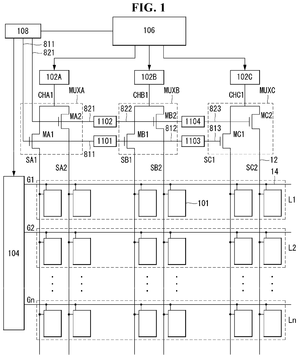
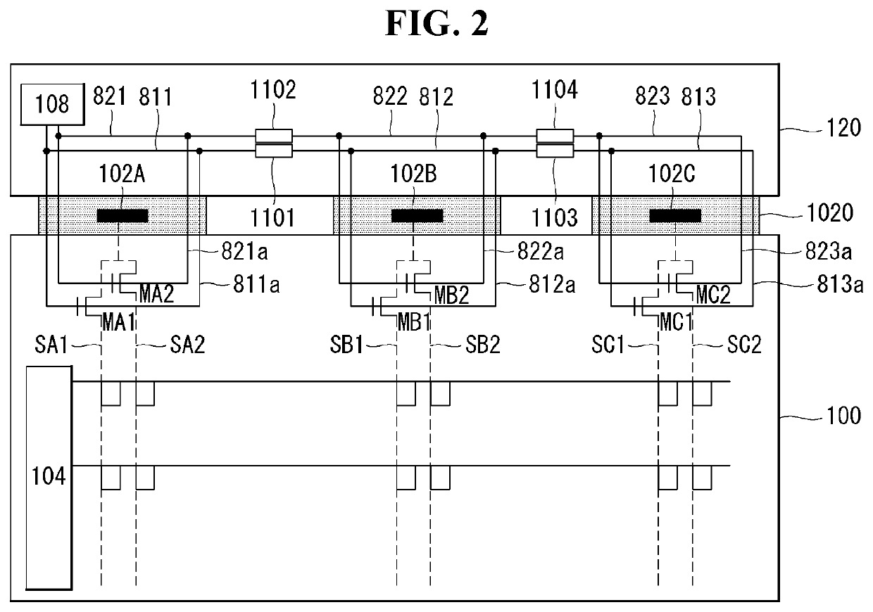
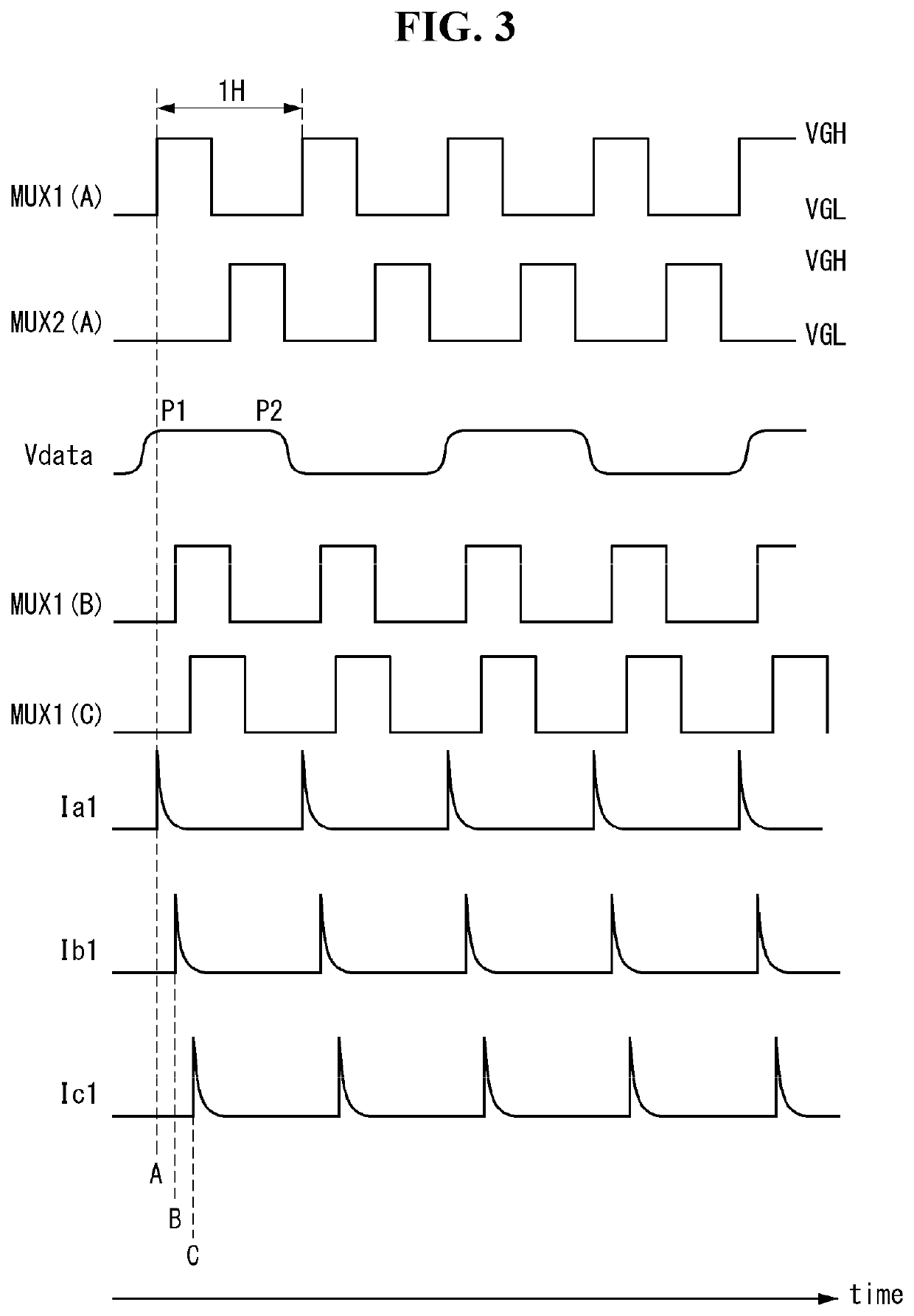
[0031]FIGS. 1 and 2 are views showing a display device according to the present disclosure, and FIG. 3 is a view showing control signals for the demultiplexers shown in FIGS. 1 and 2.

[0032]Referring to FIGS. 1 to 3, the display device of the present disclosure comprises a display panel 100 and a display panel drive circuit for writing pixel data on input image to pixels on the display panel 100. The display panel drive circuit comprises a data driver, a demultiplexer array DEMUX array, a gate array 104, etc.

[0033]The display panel 100 comprises data lines 12, gate lines 14 intersecting the data lines 12, and a pixel array where pixels are arranged in a matrix defined by the data lines 12 and the gate lines 14. The pixel array implements a screen where an input image is displayed.

[0034]The pixels in the pixel array can comprise red (R), green (G), and blue (B) sub-pixels 101 for color representation. Each pixel can further comprise white (W) sub-pixel 101 besides RGB sub-pixels 101. ...

second embodiment

[0074]FIGS. 6 to 8 are views showing a display device according to the present disclosure. FIG. 6 is a block diagram schematically showing the display device. FIG. 7 is a view showing an example in which the pixel array in FIG. 6 is divided into a plurality of blocks. FIG. 8 is a view showing in detail the touch sensors and the touch sensor driver.

[0075]Referring to FIGS. 6 to 8, the display device of the present disclosure comprises a display panel 100, an SRIC 103, a touch sensor controller 220, a parasitic capacitance controller 210, a gate driver 104, a timing controller 106, and a level shifter 108.

[0076]A pixel array 10 on the display panel 100 implements a screen where an input image is displayed. As shown in FIG. 8, the pixel array 10 comprises touch sensors 20 and sensor lines 16 connected to the touch sensors 20.

[0077]The pixels in the pixel array can comprise red (R), green (G), and blue (B) sub-pixels for color representation. Each pixel can further comprise white (W) su...


PUM


Abstract

A display device and a method of driving the same are provided. The display device includes a control signal generator that generates a control signal, a first demultiplexer that time-divides a data voltage from a first channel of a data driver and distributes the data voltage from the first channel to two or more data lines, in response to the control signal, a signal delay part that delays the control signal, and a second demultiplexer that time-divides a data voltage from a second channel of the data driver and distributes the data voltage from the second channel to other two or more data lines, in response to the control signal delayed by the signal delay part.

Description

CROSS-REFERENCE TO RELATED APPLICATIONS[0001]This application claims the priority benefit of Korean Patent Application No. 10-2018-0081290 filed in the Republic of Korea on Jul. 12, 2018, the entire contents of which are incorporated herein by reference for all purposes as if fully set forth herein.BACKGROUND OF THE INVENTIONField of the Invention[0002]The present disclosure relates to a display device with demultiplexers DEMUX placed between a data driver and data lines, and a method of driving the same.Related Art[0003]A display device generally includes a display panel with a pixel array arranged on a screen and a display panel drive circuit for writing the pixel data of input images to the pixels on the display panel. The display panel drive circuit can comprise a data driver that supplies data signals to data lines on the pixel array and a gate driver (or scan driver) that sequentially supplies a gate signal (or scan signal) synchronized with the data signals to gate lines (or ...

Claims


Application Information

Patent Timeline
Patent Type & Authority Applications(United States)
IPC IPC(8): G09G3/36
CPCG09G2330/06G09G2310/0297G09G3/3696G06F3/0412G06F3/0416G06F3/044G09G3/20H03K17/962H03K17/284G09G2320/0223G09G2330/025G09G3/3648G09G5/001G09G2310/0272G09G2230/00
Inventor KIM, DONGJUCHO, SOONDONGJANG, HOONKIM, JONGWOOHUR, JUNO
Owner LG DISPLAY CO LTD
Why Eureka
Try Eureka