
Method and circuit for detecting an arc fault

Active Publication Date: 2020-01-16
GE AVIATION SYST LTD
View PDF0 Cites 6 Cited by
  • Summary
  • Abstract
  • Description
  • Claims
  • Application Information

AI Technical Summary

Benefits of technology

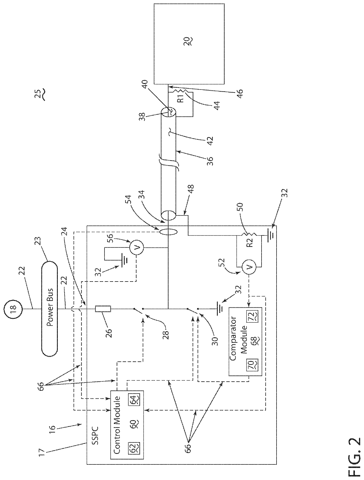
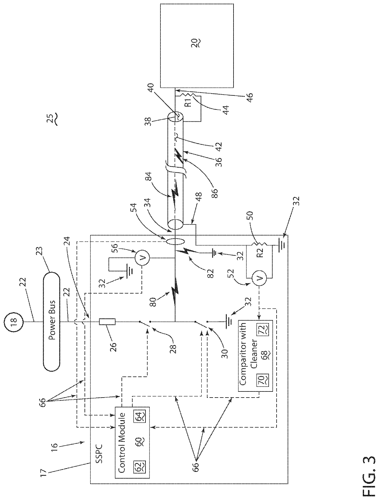
The present disclosure relates to a method and circuit for detecting and addressing faults in a circuit. The method involves sensing an electrical characteristic of the circuit, such as power, and using a controller module to determine if a fault is occurring. The controller module can then generate control signals to open or close a power switch to disable supplying power upstream of the fault. The circuit includes a sensor, controller module, and an active pull down switch that can redirect power from the source to the ground in case of a fault. The technical effects of this patent include faster detection and isolation of faults in a circuit, improved safety and reliability, and efficient maintenance and repair.

Problems solved by technology

In the event of an electrical arc fault or other failure condition, high currents might be transmitted through an unintended medium, such as air, dielectric materials, an electrically grounded connection, or the like, resulting in unexpected operations of the electrical circuit.
The unexpected operations of the electrical circuit can cause the circuit, or other unintentionally coupled medium, to fail.

Method used


Image

  • Method and circuit for detecting an arc fault
  • Method and circuit for detecting an arc fault
  • Method and circuit for detecting an arc fault

Examples


Embodiment Construction

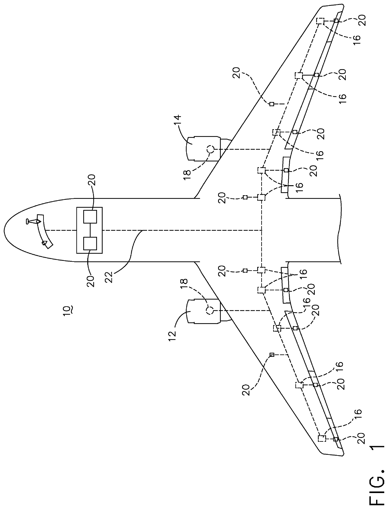
[0013]The described aspects of the present disclosure are directed to a method and apparatus associated with a power distribution network, system, circuit, or a combination thereof. One example environment where such a method and apparatus can be used includes, but is not limited to, a power distribution system for an aircraft. While this description is primarily directed toward a power distribution system for an aircraft, it is also applicable to any commercial or residential environment using a power distribution system where input power is received, acted upon (if necessary), and distributed to one or more electrical loads.

[0014]While “a set of” various elements will be described, it will be understood that “a set” can include any number of the respective elements, including only one element. As used herein, the terms “axial” or “axially” refer to a dimension along a longitudinal axis of a component or along a longitudinal axis of the component. Also as used herein, while sensors...


PUM


Abstract

A method and circuit for determining and extinguishing electrical faults includes a power supply, and electrical load, a controller module, and electrical sensors, and when the controller module does not extinguish the electrical fault, another switch blows a fuse.

Description

CROSS-REFERENCE TO RELATED APPLICATIONS[0001]This application claims the benefit of United Kingdom Patent Application No. 1811533.7, filed Jul. 13, 2018, and United Kingdom Patent Application No. 1820340.6, filed Dec. 13, 2018, both of which are incorporated herein by reference in their entirety.BACKGROUND[0002]Electrical power distribution systems manage the allocation of power from energy sources to electrical loads that consume distributed electrical power. In aircraft, gas turbine engines that propel the aircraft typically also provide mechanical energy that ultimately powers a number of different accessories such as generators, starter / generators, permanent magnet alternators (PMA), fuel pumps, and hydraulic pumps, i.e., equipment for aircraft functions other than propulsion. As well, contemporary aircraft need electrical power for electrical loads related to avionics, communications, motors, and other electric equipment.[0003]Over time, aircraft electrical power source voltage...

Claims


Application Information

Patent Timeline
IPC IPC(8): H02H7/22H02H1/00H02J4/00B64D47/00
CPCB64D47/00H02H7/222B64D2221/00H02H1/0015H02J4/00H02H7/262H02H7/263H02H3/023H02H3/385H02H3/05G01R31/00G01R31/008G01R31/08G01R31/1272G01R31/14G01R31/20G01R31/25G01R31/58H01H1/0015
Inventor COLLINS, JOHN OLIVERCOMPTON, RUSSELL MARK
Owner GE AVIATION SYST LTD
Learn More