Medical device

a medical device and proximal portion technology, applied in the field of medical devices, can solve the problems of burdensome doctor's difficulty in immediately visual recognition of medical devices in the operation room, and difficulty in immediately visual recognition of medical devices by doctors, so as to improve the visibility and identifiability of medical devices, improve the color-exhibition property of resin layers, and improve the effect of visibility

Active Publication Date: 2020-01-23
TERUMO KK
View PDF0 Cites 1 Cited by
  • Summary
  • Abstract
  • Description
  • Claims
  • Application Information

AI Technical Summary

Benefits of technology

[0009]To enhance the visibility and identifiability of a medical device by a doctor, the medical device is preferably colored with a color such as red or the like that has high visibility and can be identified relative to green or blue. For example, for a guide wire, a method of coloring a guide wire by forming a coating containing fluororesin layer, which is blended with an organic pigment representing red, on an outer surface of a core member (elongated body) of a guide wire may be considered. The fluororesin layer on an outer surface of the core member (elongated body) of the guide wire is generally formed by coating the coating solution containing the fluororesin dispersed in a solvent on the core member and then performing baking.
[0010]However, in general, since baking for forming a fluororesin layer on an outer surface of a core member of a guide wire is carried out at high temperatures, there has been a case in which the organic pigment is discolored, thus impairing the color-exhibition property of a resin layer. Furthermore, when the coating includes large amounts of an organic pigment relative to the fluororesin, it is necessary that the dispersant for dispersing the organic pigment is also blended in large amounts. With the dispersant blended in large amounts, there has been a case in which the adhesion property of the fluororesin layer to a core member and to other resin layer to be laminated is impaired, and thus the coating is easily peeled off.
[0011]The medical device disclosed here has high visibility on non-woven fabric having a color such as green, blue, or the like, excellent identifiability from other medical devices having colors such as green, blue, or the like, and also a high adhesion property and strength of a coating.

Problems solved by technology

Meanwhile, since the medical device to be inserted to a lumen or a tissue of a living body has a small diameter, it may be sometimes difficult to immediately visually recognize the medical device in an operation room.
If a medical device has a color hue which belongs to the same color group as the non-woven fabric, the medical device and background color would have the same color so that there may be a case in which a doctor has a difficulty visually recognizing the medical device immediately.
However, due to the long length of a guide wire, the handle part for a doctor is quite apart from the proximal portion of a guide wire so that a work involved in confirming the marker at the proximal portion of a guide wire would be burdensome to a doctor.
However, in general, since baking for forming a fluororesin layer on an outer surface of a core member of a guide wire is carried out at high temperatures, there has been a case in which the organic pigment is discolored, thus impairing the color-exhibition property of a resin layer.
With the dispersant blended in large amounts, there has been a case in which the adhesion property of the fluororesin layer to a core member and to other resin layer to be laminated is impaired, and thus the coating is easily peeled off.

Method used

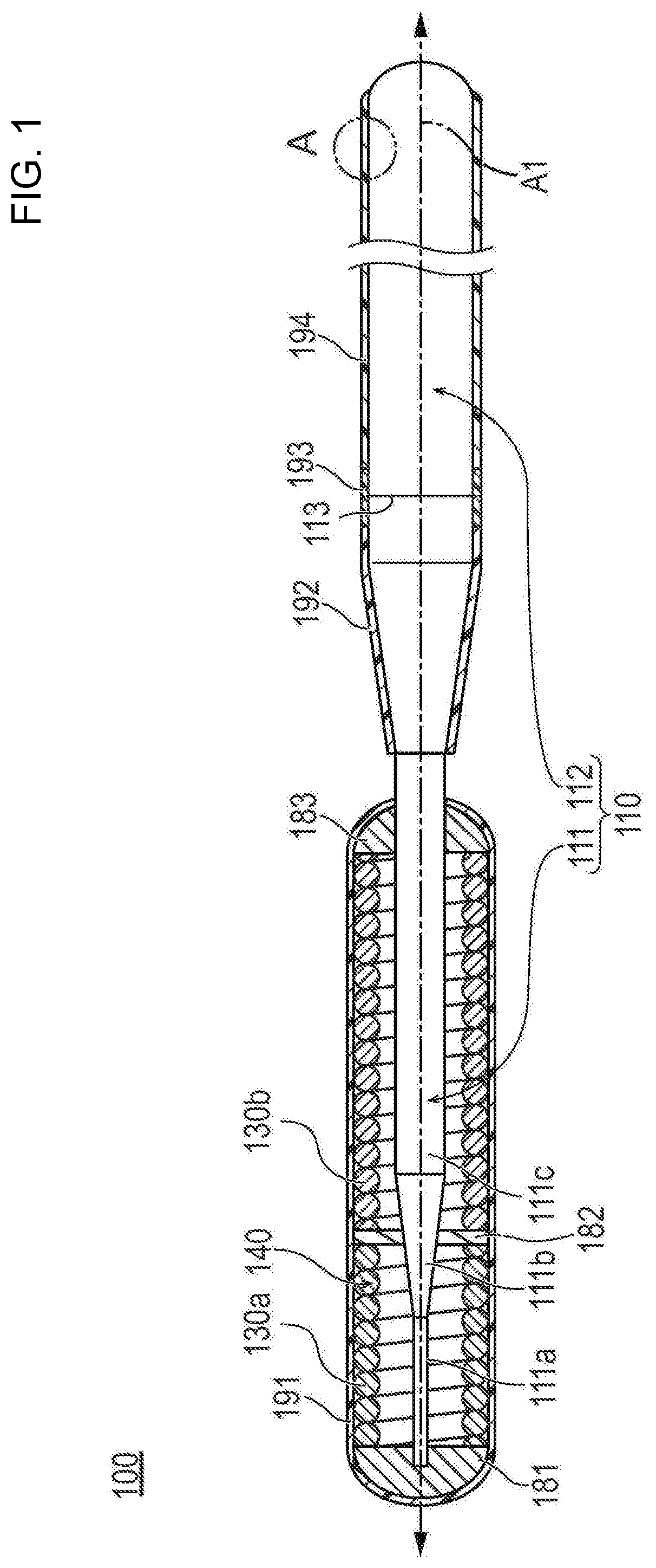

Image

  • Medical device
  • Medical device

Examples


example 1

[0109][Preparation of Coating Solution for Forming the First Layer]

[0110]32.0 g of a quinacridone-based organic pigment (C.I. Pigment Violet 19, average particle diameter of 430 nm) (relative to the solid content: 36.8% by weight), 8.0 g of titanium oxide (C.I. Pigment White 6, rutile type, average particle diameter of 250 nm) (relative to the organic pigment: 25% by weight, relative to the solid content: 9.2% by weight), 132.0 g of methyl isobutyl ketone as a solvent, 5.4 g of polytetrafluoroethylene (PTFE, average particle diameter of 0.20 μm, melting point of 327° C.), 16.1 g of tetrafluoroethylene-hexafluoropropylene copolymer (FEP, average particle diameter of 0.20 μm, melting point of 270° C.), 21.5 g of polyphenylene sulfide resin as a binder resin, 3.2 g of DISPERBYK 2055 (manufactured by BYK-Chemie) as a dispersant (relative to the organic pigment and the titanium oxide: 8% by weight, relative to the solid content: 3.7% by weight), and 0.8 g of GARAMITE 7305 as a thickening...

example 2

[0116]A guide wire was obtained in the same manner as Example 1 except that, for preparing a coating solution for forming the first layer, the blending amount of the quinacridone-based organic pigment is changed to 20.0 g (relative to the solid content: 23.0% by weight) and the blending amount of the titanium oxide is changed to 20.0 g (relative to the organic pigment: 100% by weight, relative to the solid content: 23.0% by weight).

example 3

[0117]A guide wire was obtained in the same manner as Example 1 except that, for preparing a coating solution for forming the first layer, the blending amount of the quinacridone-based organic pigment is changed to 16.0 g (relative to the solid content: 18.4% by weight) and the blending amount of the titanium oxide is changed to 24.0 g (relative to the organic pigment: 150% by weight, relative to the solid content: 27.6% by weight).


PUM

PropertyMeasurementUnit
distanceaaaaaaaaaa
thicknessaaaaaaaaaa
thicknessaaaaaaaaaa

Abstract

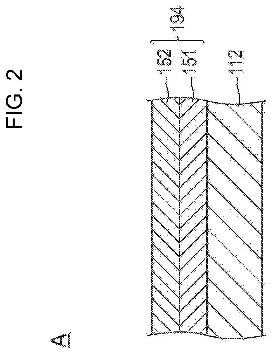
The disclosed medical device has high visibility on non-woven fabric having a color such as green, blue, or the like, excellent identifiability from other medical devices having colors such as green, blue, or the like, and also a high adhesion property and strength of a coating. The medical device comprises an elongated body and a resin layer covering at least a proximal portion of the elongated body. The resin layer is comprised of a first layer which includes a first fluororesin, an organic pigment and titanium oxide, and a second layer which is formed on the first layer and includes a second fluororesin.

Description

CROSS-REFERENCES TO RELATED APPLICATIONS[0001]This application is a continuation of International Application No. PCT / JP2018 / 012148 filed on Mar. 26, 2018, and claims priority to Japanese Patent Application No. 2017-067868 filed on Mar. 30, 2017, the entire content of both of which is incorporated herein by reference.TECHNICAL FIELD[0002]The present invention generally relates to a medical device and method for fabricating or producing a medical device.BACKGROUND ART[0003]A guide wire is a medical device which is employed for guiding a catheter used for percutaneous transluminal coronary angioplasty (PTCA), cardiovascular imaging test, or the like for treatment of a stenosis in coronary artery of heart. As a part of percutaneous transluminal coronary angioplasty, the guide wire is inserted in combination with a balloon catheter, in a state in which the guide wire protrudes beyond the distal end of the balloon catheter, to the vicinity of a stenosis in coronary artery as a target sit...

Claims


Application Information

Patent Timeline
Patent Type & Authority Applications(United States)
IPC IPC(8): A61L31/10A61L31/16A61L31/08
CPCA61L31/082A61L2420/06A61L2300/442A61L2420/08A61L2420/02A61L31/10A61L31/16A61M25/00A61M25/09A61L2420/04A61L29/085A61L29/106A61L29/14A61L31/088A61L31/14C08L27/18C08L27/12
Inventor OIWA, TOMOYA
Owner TERUMO KK
Why Eureka
Try Eureka