High-feed cutting insert and cutting tool equipped with same
Active Publication Date: 2020-01-23
KORLOY
View PDF0 Cites 1 Cited by
Summary
Abstract
Description
Claims
Application Information
AI Technical Summary
This helps you quickly interpret patents by identifying the three key elements:
Problems solved by technology
Method used
Benefits of technology
Benefits of technology
[0024]As described above, the high feed cutting insert and the cutting tool equipped with the same according to embodiments of the present disclosure have the following effects.
[0025]According to an embodiment of the present disclosure, there is provided a technical configuration which includes a short cutting edge, a long cutting edge, an ascending corner cutting edge, and a descending corner cutting edge, in which, the short cutting edge and the long cutting edge, when viewed towards the main surface, form an obtuse angle with respect to the ascending corner cutting edge interposed therebetween and form an acute angle while the descending corner cutting edges are interposed therebetween. Accordingly, the entering angle of an approximate 5 to 15 degrees can be provided through the obtuse angle, without requiring the cutting insert be inclined at an excessive angle with respect to the cutting tool in order to provide the entering angle and back taper when mounted to the cutting tool, and accordingly, it is possible to provide a sufficient entering angle while ensuring rigidity of the bottom part of a cutting tool. In other words, since a screw fastening hole formed in the cutting tool can be formed at a sufficient distance from the bottom surface of the cutting tool, while a sufficient entering angle can still be provided, it
Problems solved by technology
However, since the conventional tangential cutting insert 10 has the front surface 20 that is in rectangular shape, as shown in FIG. 15, in order to provide the entering angle θ1 and the back taper θ2 when mounted on the cutting tool 50, the cutting insert 10 has to be mounted at excessive angles with respect to the cutting tool 50 such that the screw fastening hole 51 formed in the cutting tool 50 is placed close to the bottom surface 52 of the cutting tool 50, resulting in a problem of lowered rigidity of the bottom part of the cutting
Method used
Image
Click on the blue label to locate the original text in one second.
Reading with bidirectional positioning of images and text.
Examples
Example
[0065]Hereinafter, the cutting tool 200 according to the first embodiment of the present disclosure will be described in detail with reference to FIG. 6.
[0066]The cutting tool 200 according to the first embodiment of the present disclosure is a type of cutting tool to which the high feed cutting insert 100 according to the first embodiment of the present disclosure described above is mounted, and it includes a first seat surface 201, a second seat surface 202, and a third seat surface 203, which are provided in a pocket portion thereof.
[0067]The first seat surface 201 is where the sub-surface 112 of the high feed cutting insert 100 described above is placed, the second seat surface 202 is where the short side surface 120 of the high feed cutting insert 100 described above is placed, and the third seat surface 203 is where the long side surface 130 of the high feed cutting insert 100 described above is placed.
[0068]In particular, the third seat surface 203 may be inclined in a direct...
Example
[0069]Hereinafter, a high feed cutting insert 2100 according to a second embodiment of the present disclosure will be described in detail with reference to FIGS. 8 to 10.
[0070]FIG. 8 is a cross-sectional view of a main part schematically showing the high feed cutting insert according to the second embodiment of the present disclosure, FIG. 9 is a view schematically showing the high feed cutting insert of FIG. 8 when viewed from the directions of the main surface and the sub-surface (FIG. 9A), when viewed from the direction of the short side surface (FIG. 9B), and when viewed from the direction of the long side surface (FIG. 9C), and FIG. 10 is a cross-sectional view showing a main part of the high feed cutting insert of FIG. 9B taken along the line X-X.
[0071]As shown in FIGS. 8 to 10, the high feed cutting insert 2100 according to the second embodiment of the present disclosure is almost the same as the first embodiment of the present disclosure described above, except for the chang...
Example
[0075]Hereinafter, a high feed cutting insert 3100 according to a third embodiment of the present disclosure will be described in detail with reference to FIGS. 11 to 13.
[0076]FIG. 11 is a perspective view schematically showing the high feed cutting insert according to the third embodiment of the present disclosure, FIG. 12 is a view schematically showing the high feed cutting insert of FIG. 11 when viewed from the direction of the main surface (FIG. 11A), when viewed from the direction of the short side surface (FIG. 11B), and when viewed from the direction of the long side surface (FIG. 11C), and FIG. 13 is a cross-sectional view showing a main part of the high feed cutting insert of FIG. 12C taken along line XIII-XIII.
[0077]As shown in FIGS. 11 to 13, the high feed cutting insert 3100 according to the third embodiment of the present disclosure is almost the same as the first embodiment of the present disclosure described above, except for the changes in the shapes of a sub-surfac...
PUM
Abstract
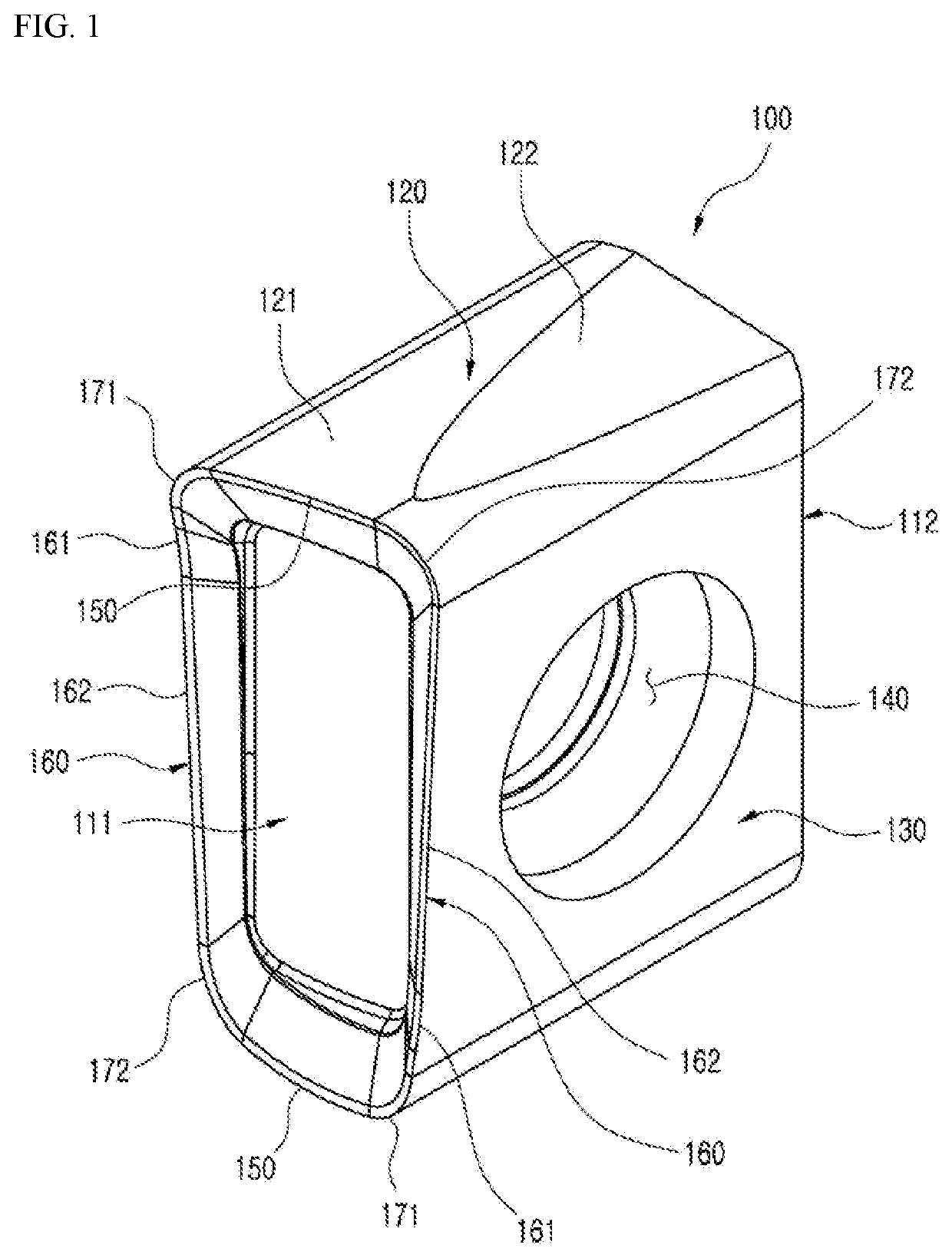
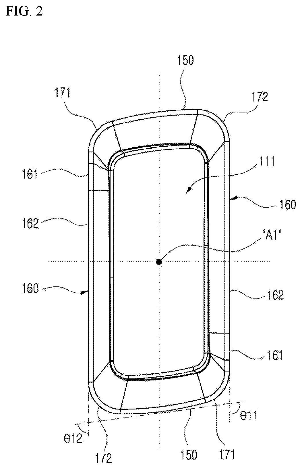
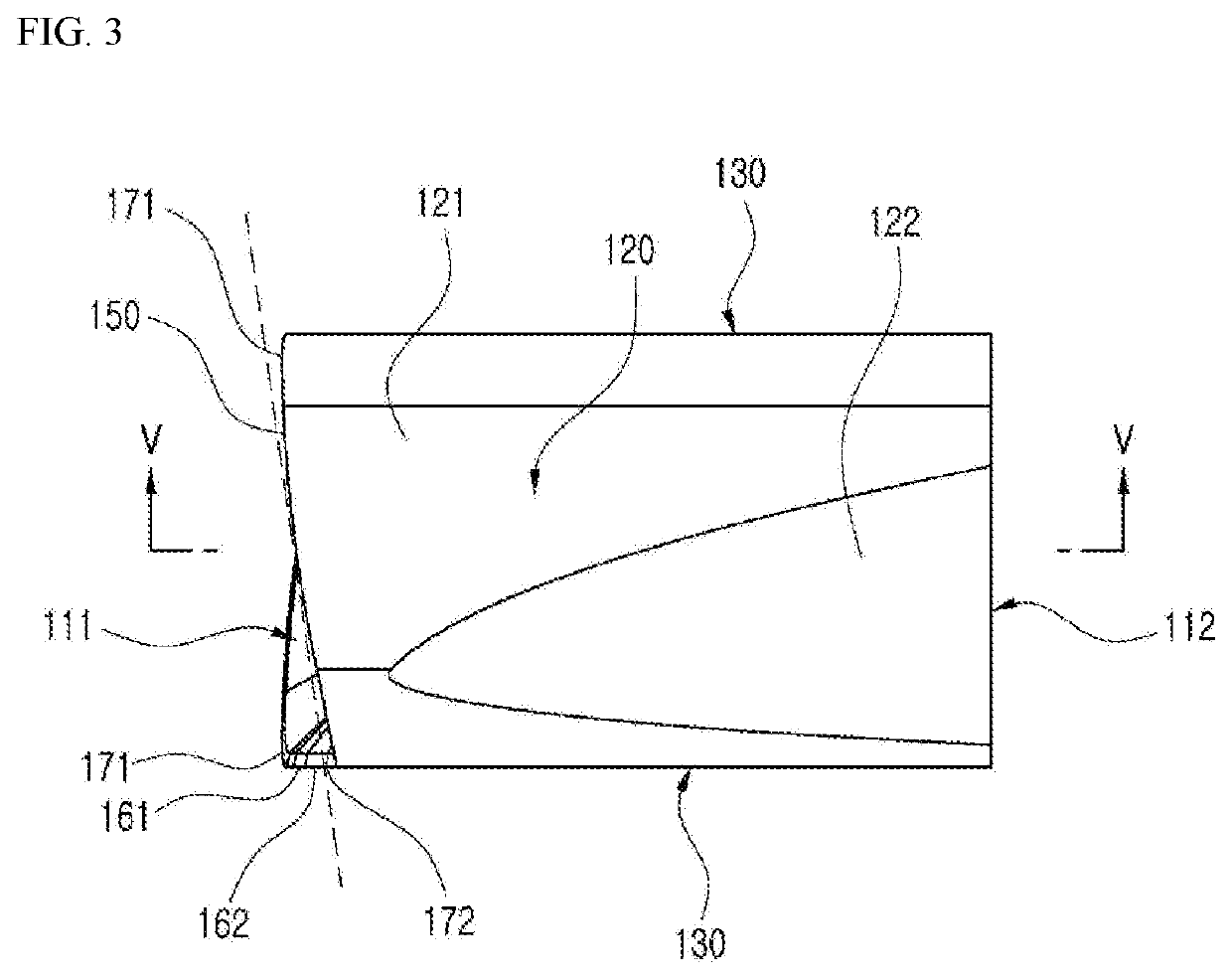
The present disclosure's technical object is to provide a high feed cutting insert capable of providing a sufficient entering angle while ensuring rigidity of a cutting tool's bottom part. For this, the high feed cutting insert of the present disclosure comprises a short cutting edge provided on a boundary portion between a main surface and a short side surface, a long cutting edge provided on a boundary portion between the main surface and a long side surface, two ascending corner cutting edges connecting the short cutting edge and the long cutting edge, and placed on one diagonal position, and two descending corner cutting edges placed on the other diagonal position and having the height lower than that of the ascending corner cutting edges, wherein the short cutting edge and the long cutting edge, when viewed towards the main surface, form an obtuse angle while the ascending corner cutting edges are interposed therebetween and form an acute angle while the descending corner cutting edges are interposed therebetween.
Description
TECHNICAL FIELD[0001]The present disclosure relates to a high feed cutting insert having a high machining speed and a cutting tool equipped with the same.BACKGROUND ART[0002]Generally, a cutting insert is fastened to a cutting tool mounted on a machine tool and is used for machining a workpiece made of iron, non-ferrous metal, non-metal material, and the like.[0003]FIG. 14 is a perspective view showing a conventional tangential cutting insert, FIG. 15 is a view schematically showing a state in which the tangential cutting insert of FIG. 14 is mounted to a cutting tool, and FIG. 16 is a bottom view showing the radial rake angle of the cutting insert of FIG. 14 when mounted to the cutting tool.[0004]An example of the conventional tangential cutting insert 10 is disclosed in EP02214857 A1, which includes, as shown in FIG. 14, an upper surface 12, a lower surface 14, two side surfaces 24 connecting between the upper surface and the lower surface, a front surface 20 connecting between th...
Claims
Application Information
Patent Timeline
Application Date:The date an application was filed.
Publication Date:The date a patent or application was officially published.
First Publication Date:The earliest publication date of a patent with the same application number.
Issue Date:Publication date of the patent grant document.
PCT Entry Date:The Entry date of PCT National Phase.
Estimated Expiry Date:The statutory expiry date of a patent right according to the Patent Law, and it is the longest term of protection that the patent right can achieve without the termination of the patent right due to other reasons(Term extension factor has been taken into account ).
Invalid Date:Actual expiry date is based on effective date or publication date of legal transaction data of invalid patent.

