Aircraft Water Tank and Method for Manufacturing Same
a technology for aircraft water tanks and water tanks, which is applied in the direction of aircraft crew accommodation, container discharging methods, transportation and packaging, etc., can solve the problems of increasing the efficiency of manufacturing aircraft water tanks, increasing the volume of adhesives to fill the level difference, and increasing the stress concentration. concentration, increase the durability of aircraft water tanks, and increase work efficiency
- Summary
- Abstract
- Description
- Claims
- Application Information
AI Technical Summary
Benefits of technology
Problems solved by technology
Method used
Image

Examples
first embodiment
[0046]Hereinafter, an aircraft water tank according to an embodiment of the present technology will be described together with a method for manufacturing the same.
[0047]First, a first embodiment will be described with reference to FIGS. 1 to 3.
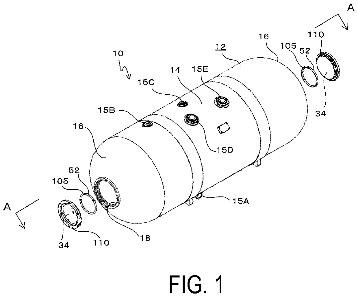
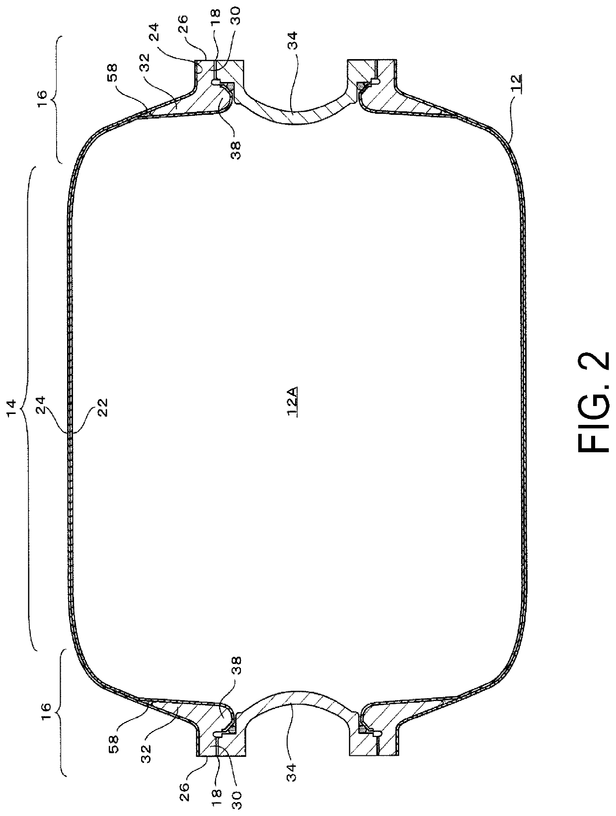
[0048]As illustrated in FIGS. 1 and 2, an aircraft water tank 10 installed in an aircraft and containing drinking water includes a tank body 12. The interior of the tank body 12 is a water containing space 12A.
[0049]The tank body 12 includes a cylindrical portion 14 and dome portions 16 provided on both sides of the cylindrical portion 14. In the present embodiment, the outer circumferential surface of the dome portion 16 is formed with a uniform stress surface.
[0050]An opening 18 for cleaning the interior of the tank body 12 is provided at the center of the dome portion 16 on either side, and the opening 18 is opened and closed by a lid 34.
[0051]Furthermore, a water supply tank port 15A communicating with the interior of the tank body 12 is p...
second embodiment
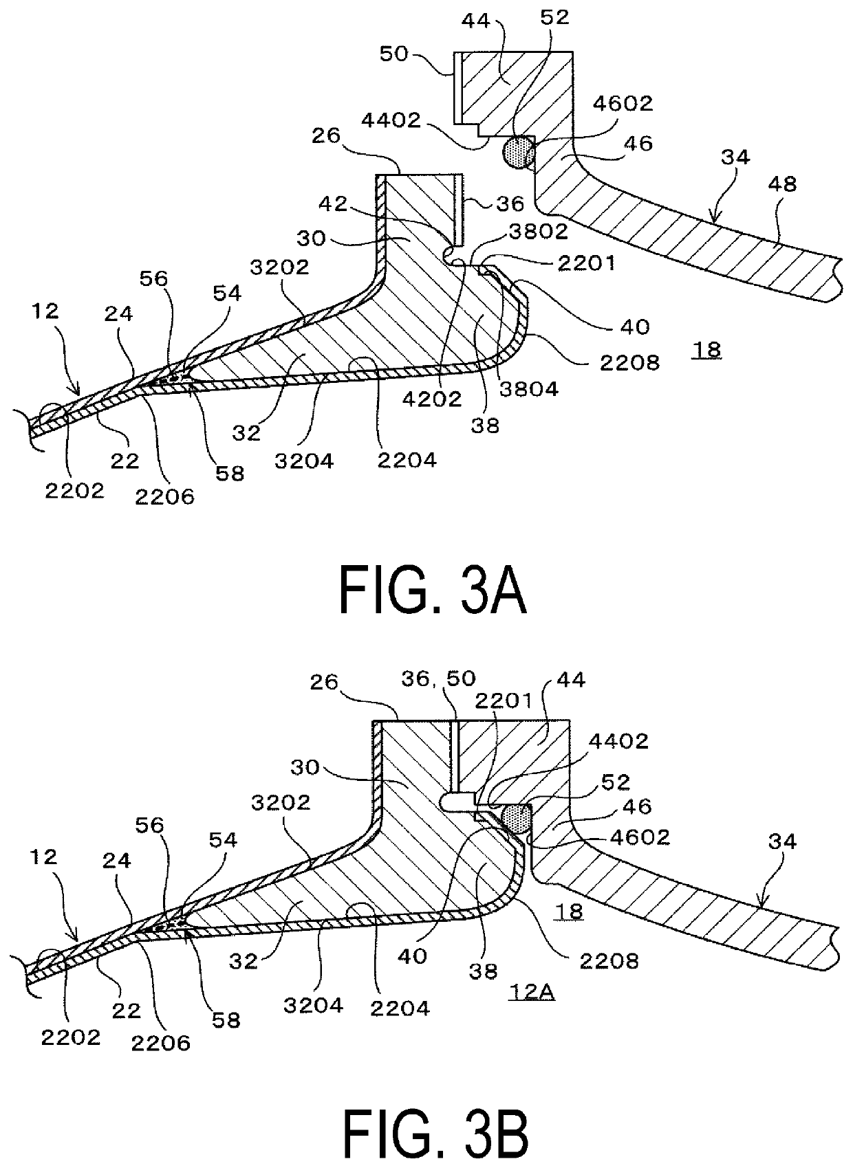
[0105]Next, a second embodiment will be described with reference to FIGS. 4A and 4B.
[0106]Note that, this explanation of the second embodiment shall focus on differences from the first embodiment. Therefore, portions and members that are the same as in the first embodiment have the same reference signs and their explanations shall be omitted.
[0107]The second embodiment is different from the first embodiment in that the bent portion 2206 is positioned in the vicinity of the outer circumferential end of the skirt portion 32 and radially inward of the skirt portion 32, and the inner liner 22, in addition to being connected to the conical surface portion 2204 via the bent portion 2206, includes a connection curved surface portion 2210 which is continuously connected to the uniform stress surface portion 2202. Other points such as using an epoxy resin, for example, when bonding the inner circumferential surface of the skirt portion 32 and the outer circumferential surface of the inner li...
PUM
| Property | Measurement | Unit |
|---|---|---|
| Diameter | aaaaa | aaaaa |
| Stress optical coefficient | aaaaa | aaaaa |
| Tension | aaaaa | aaaaa |
Abstract
Description
Claims
Application Information
 - Generate Ideas
- Intellectual Property
- Life Sciences
- Materials
- Tech Scout
- Unparalleled Data Quality
- Higher Quality Content
- 60% Fewer Hallucinations
Browse by: Latest US Patents, China's latest patents, Technical Efficacy Thesaurus, Application Domain, Technology Topic, Popular Technical Reports.
© 2025 PatSnap. All rights reserved.Legal|Privacy policy|Modern Slavery Act Transparency Statement|Sitemap|About US| Contact US: help@patsnap.com