Ultrasonic welding member and ultrasonic welding method

a technology of ultrasonic welding and ultrasonic welding, which is applied in the field of ultrasonic welding members and ultrasonic welding methods, can solve the problems of low productivity of ultrasonic welding nets, difficult to form rib-shaped protrusions thereon, and substantially impossible to form rib-shaped protrusions, etc., and achieves low design restriction in thickness , the effect of reducing the volume of ultrasonic welding members and high manufacturing efficiency

Inactive Publication Date: 2020-01-30
TSUCHIYA CORP +1
View PDF0 Cites 0 Cited by
  • Summary
  • Abstract
  • Description
  • Claims
  • Application Information

AI Technical Summary

Benefits of technology

[0033]The ultrasonic welding member according to the present invention is handled independently of the first member and the second member which are to be welded, whereby there is no need to provide in advance rib-shaped protrusions for welding.
[0034]Further, the ultrasonic welding member has less design restrictions in thickness in a direction between two members to be welded (especially when a mesh is adopted), and the volume of the ultrasonic welding member can be reduced. Thus, the ultrasonic welding member provides high manufacturing efficiency, and can reduce manufacturing time and cost.
[0035]Furthermore, the ultrasonic welding member is formed such that: bonding places (weld start points) between the ultrasonic welding member and the surfaces to be welded are discontinuously present in at least a part thereof; non-bonding places are open to the outside so as to ensure an air path; and a ratio of areas between bonding places and non-bonding places is adjusted to fall within a predetermined range. Thus, voids are less likely to remain in the welded part, and high airtightness of the bonded part can be obtained, whereby sufficient weld strength can be ensured.
[0036]These effects are similarly obtained when the above ultrasonic welding method is used.

Problems solved by technology

However, a method for forming, in advance, rib-shaped protrusions integrally on one of the thermoplastic resin members to be welded is limited to a molding method such as injection molding, and if the surface of the member to be welded has a complex shape, it is very difficult to form rib-shaped protrusions thereon.
Therefore, the composite material has a problem that it is substantially impossible to form the rib-shaped protrusions.
The ultrasonic welding net described above has low productivity, and thus, has increased cost.
Furthermore, since the net has a flat structure, air is trapped in the welded part and voids are likely to remain, resulting in causing a disadvantage that the weld strength is reduced, and the appearance is deteriorated.

Method used


Image

  • Ultrasonic welding member and ultrasonic welding method
  • Ultrasonic welding member and ultrasonic welding method
  • Ultrasonic welding member and ultrasonic welding method

Examples


example 1

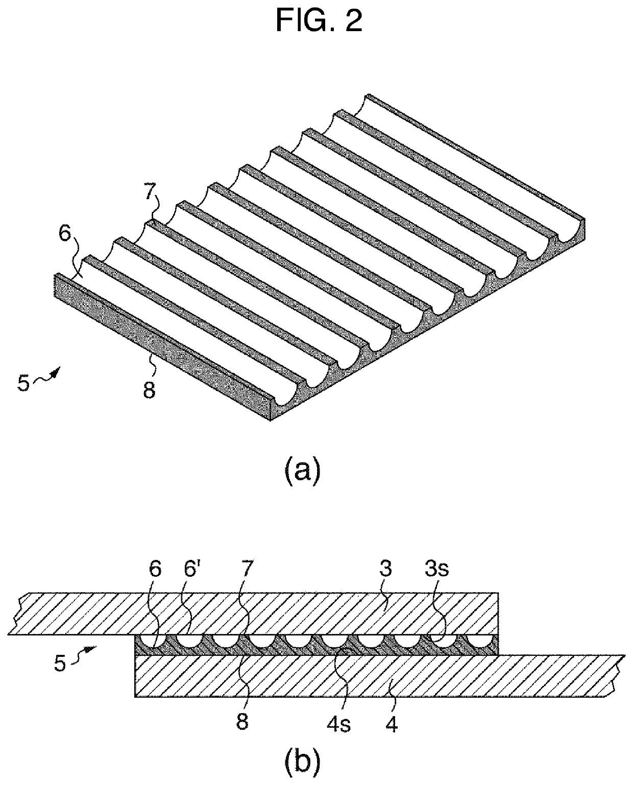
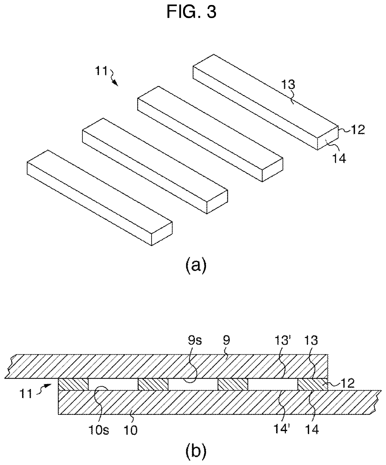
[0097]Flat plates made of PEEK resin were used as a pair of thermoplastic resin plates serving as members to be welded.

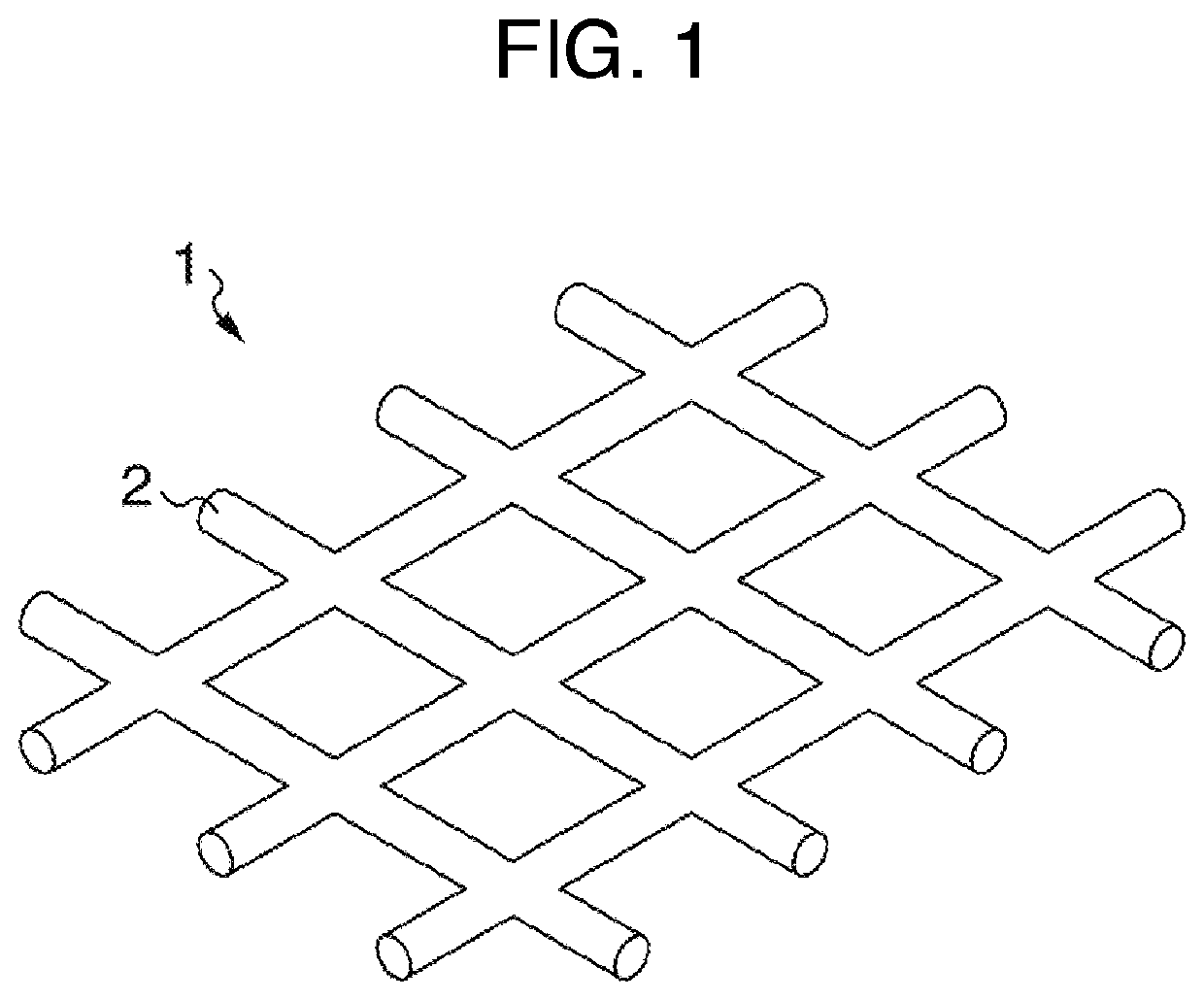
[0098]A plain weave mesh similarly made of PEEK resin and having a uniform mesh opening as a whole was used as the ultrasonic welding mesh, the mesh having a thread outer diameter of 0.2 mm and a mesh opening of 0.3 mm.

[0099]Ultrasonic welding was performed using these materials, and the cross section of the welded part was observed.

example 2

[0100]Ultrasonic welding was performed in the same manner as in Example 1 except that an ultrasonic welding mesh with a thread outer diameter of 0.4 mm and a mesh opening of 0.45 mm was used, and the cross section of the welded part was observed.

example 3

[0101]Ultrasonic welding was performed in the same manner as in Example 1 except that an ultrasonic welding mesh with a thread outer diameter of 0.5 mm and a mesh opening of 1.0 mm was used, and the cross section of the welded part was observed.


PUM

PropertyMeasurementUnit
outer diameteraaaaaaaaaa

Abstract

Disclosed are: an ultrasonic welding member which is independent of a first member and a second member and which is held between a surface to be welded of the first member and a surface to be welded of the second member prior to ultrasonic welding between the surface to be welded of the first member and the surface to be welded of the second member having a shape parallel to or fitted into the surface to be welded of the first member, the ultrasonic welding member characterized by including a thermoplastic resin and satisfying a discontinuous forming requirement, an outside opening requirement, and a bonding place reduction requirement; and an ultrasonic welding method using the ultrasonic welding member. The ultrasonic welding member may include a plurality of streaks at least in a part thereof. The ultrasonic welding member may be a substantially lattice-shaped fabric or textile mesh at least in a part thereof. When the ultrasonic welding member is held between the surface to be welded of the first member and the surface to be welded of the second member, crossing parts of threads of the mesh may form a bonding place between the ultrasonic welding member and the surface to be welded of the first member and a bonding place between the ultrasonic welding member and the surface to be welded of the second member.

Description

TECHNICAL FIELD[0001]The present invention relates to an ultrasonic welding member and an ultrasonic welding method. More specifically, the present invention relates to an ultrasonic welding member independent of a first member and a second member which are to be welded, and an ultrasonic welding method using the same.BACKGROUND ART[0002]As a welding method for welding two members which are made of a thermoplastic resin, an ultrasonic welding method for welding members by applying ultrasonic vibration has been used widely. In this regard, there has been generally known a method in which a rib is integrally formed in advance in one of thermoplastic resins to be welded, and this rib pattern is used as a weld start point when ultrasonic vibration is applied.[0003]However, a method for forming, in advance, rib-shaped protrusions integrally on one of the thermoplastic resin members to be welded is limited to a molding method such as injection molding, and if the surface of the member to ...

Claims


Application Information

Patent Timeline
Patent Type & Authority Applications(United States)
IPC IPC(8): B29C65/00B29C65/08
CPCB29C65/08B29C66/232B29C66/71B29C66/1122B29C66/43B29C66/73921B29C66/3024B29C65/5057B29C65/4815B29C66/832B29C65/5028B29C66/30341B29C65/5071B29C66/21B29K2105/206B29C66/234B29C66/7212B29K2071/00B29K2023/12B29K2307/04
Inventor YOSHIDA, OSAMUHAYASHI, HIROAKITSUJI, KOTAROHORIZONO, HIDEKIISHIKAWA, NAOMOTOTAKAYANAGI, TOSHIYUKI
Owner TSUCHIYA CORP
Why Eureka
Try Eureka