

Methods for biomechanical mapping of the female pelvic floor
a biomechanical mapping and pelvic floor technology, applied in the field of female pelvic tissue characterization methods, can solve the problems of poor sensitivity, high subjectiveness, and inability to precisely identify the defective structures (muscles, ligaments) in the pelvic floor, and achieve the effect of avoiding the formation of abnormalities, and avoiding abnormalities
Inactive Publication Date: 2020-02-06
ADVANCED TACTILE IMAGING
View PDF0 Cites 3 Cited by
- Summary
- Abstract
- Description
- Claims
- Application Information
AI Technical Summary
Benefits of technology
[0008]A need therefore exists for a method of creating a comprehensive biomechanical mapping of the pelvic floor tissues using an extended set of predetermined parameters, which may open a new possibility in biomechanical assessment and monitoring of pelvic floor conditions.
[0009]The object
Problems solved by technology
While physical examination helps the clinician to describe the extent of pelvic disease conditions, it does not help in discerning the initial stage of abnormality development from the normal conditions or specifically identify the defective structures (muscles, ligaments) in the pelvic floor.
D
Method used
View moreImage
Smart ImageViewing Examples

Examples
 PUM
 Abstract
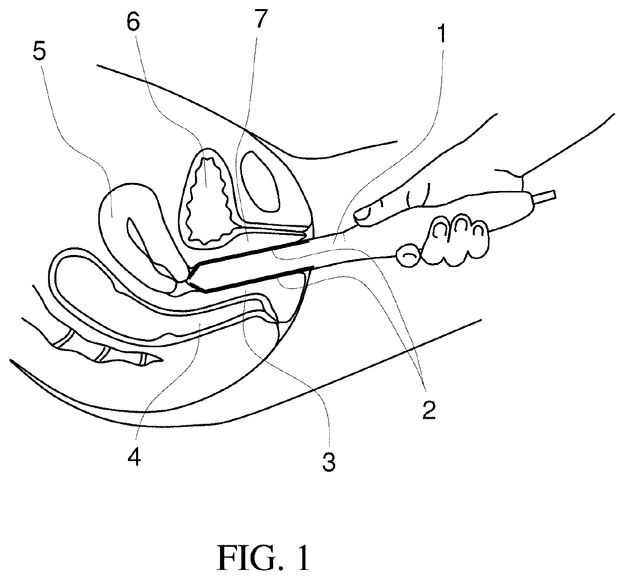
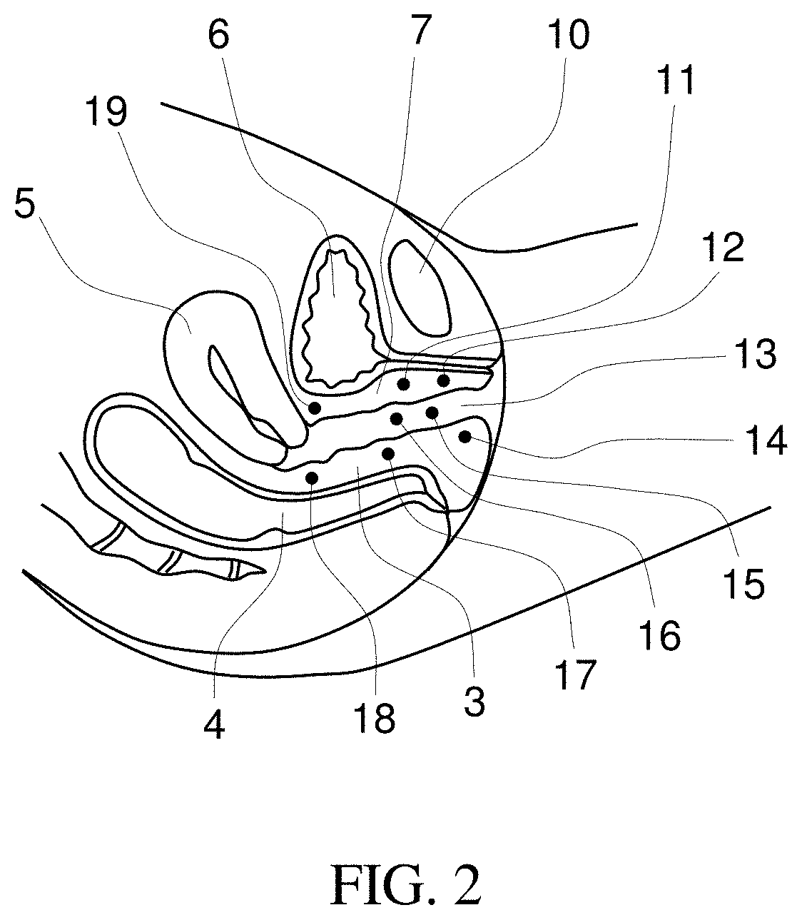
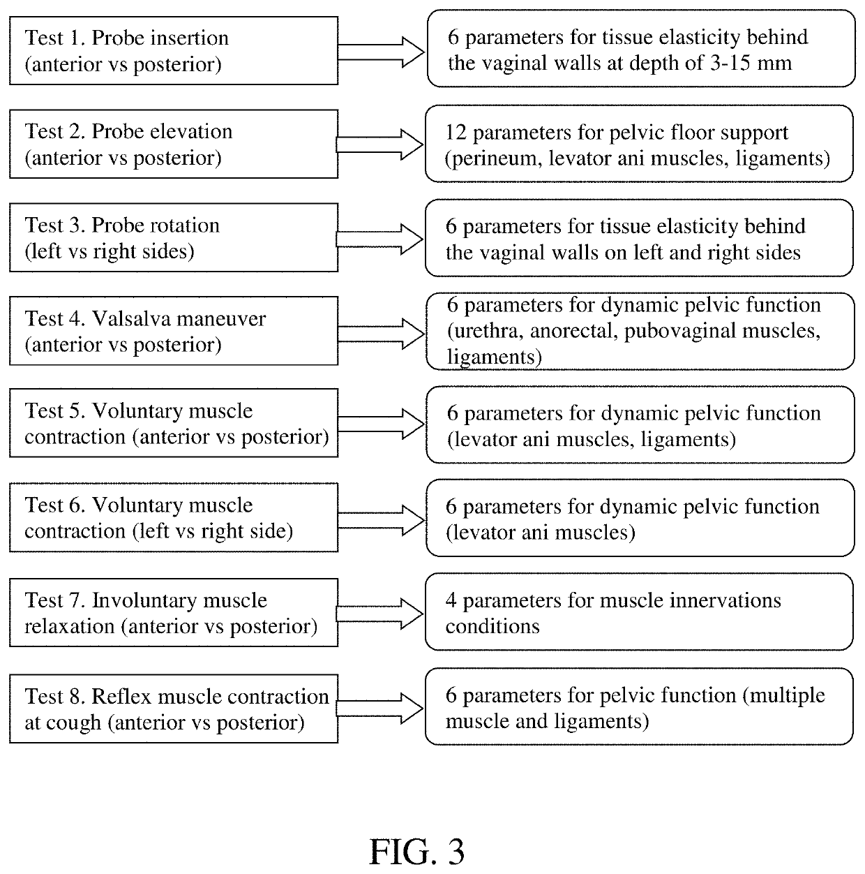
Methods for biomechanical mapping of the female pelvic floor may include the steps of inserting a vaginal tactile imaging probe into vagina; recording tactile responses for vaginal walls during vaginal wall deformation by moving a probe as well as dynamic pressure patterns during voluntary or involuntary muscle contractions in multiple test procedures; followed by calculating multiple biomechanical parameters characterizing vaginal tissue elasticity, pelvic support structures and dynamic pelvic functions. Individual biomechanical parameters may be visually represented by positioning their value within the established physiological parameter ranges varying from normal to diseased conditions. The methods may be used for identification of pelvic floor tissues with low elasticity, deteriorated or damaged pelvic support muscles and ligaments, and muscles with low contractive capability. Other methods include the steps of collecting clinical history and completing gynecological examinations of the pelvic floor and calculating probabilities of treatment success for pelvic diseases depending on a proposed treatment using a predictive mathematical model.
Description
GOVERNMENT-SPONSORED RESEARCH[0001]This invention was made with the US Government support under grant No-SB1AG034714 awarded by the National Institute on Aging, National Institutes of Health. The Government has certain rights in this invention.BACKGROUND OF THE INVENTION[0002]The present invention generally relates to characterization methods for female pelvic tissues. Specifically, the invention describes methods and devices for characterizing vaginal tissue elasticity, pelvic floor support structures and dynamic pelvic functions.[0003]Recent survey identified as the highest priority research questions pertaining to pathophysiology and treatments of pelvic organ prolapse (POP). According to the survey, mechanistic research on pelvic supportive structures, clinical trials to optimize outcomes after POP surgery and evidence-based quality measures for POP outcomes are among the major focus areas [Siddiqui N Y, Gregory W T, Handa V L, DeLancey J O L, Richter H E, Moalli P, Barber M D, ...
Claims
Login to View More Application Information
Patent Timeline
 IPC IPC(8): A61B5/00
CPCA61B5/6846A61B5/4337A61B8/0858A61B5/035A61B5/227A61B5/6867A61B8/12A61B2562/0247A61B2562/046
InventorEGOROV, VLADIMIR
OwnerADVANCED TACTILE IMAGING