
MEMS microphone device and electronics apparatus

Active Publication Date: 2020-02-06
WEIFANG GOERTEK MICROELECTRONICS CO LTD
View PDF0 Cites 12 Cited by
  • Summary
  • Abstract
  • Description
  • Claims
  • Application Information

AI Technical Summary

Benefits of technology

The patent aims to minimize the impact of outside particles on the MEME microphone element. The technical effect is to reduce interference and improve the quality of the audio signal captured by the microphone.

Problems solved by technology

Dusts or particles can enter the acoustic port and thus the performance of the MEMS microphone device may be degraded.
However, this will degrade the performance of the MEMS microphone device, such Signal-Noise-Ratio (SNR).
By using such a filter, killer particles for a MEMS microphone element of 2˜5 μm, such as PM 2.5 particles, cannot be blocked out efficiently.

Method used


Image

  • MEMS microphone device and electronics apparatus
  • MEMS microphone device and electronics apparatus

Examples


first embodiment

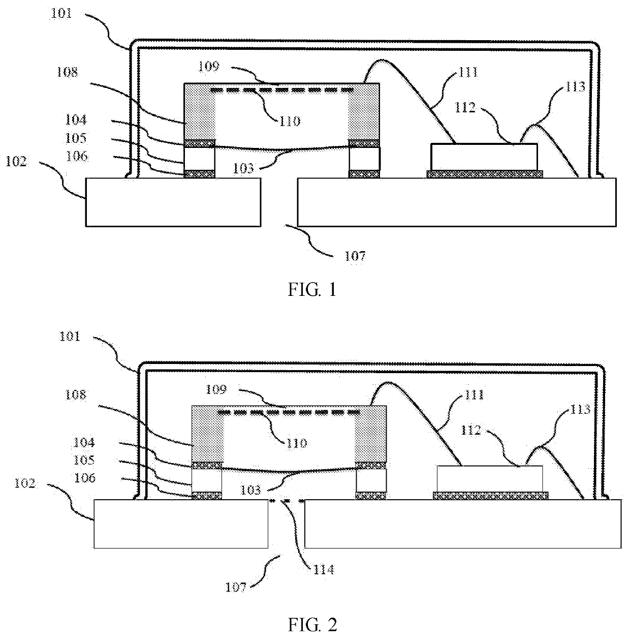
[0036]FIG. 1 shows a schematic diagram of a MEMS microphone device according to a first embodiment of the present invention.

[0037]As shown in FIG. 1, the MEMS microphone device comprises a substrate 102, a MEMS microphone element 108, a cover 101 and an acoustic port 107 for the MEMS microphone element 108. The MEMS microphone element 108 is placed on the substrate 102. The cover 101 encapsulates the MEMS microphone element 108 together with the substrate 102.

[0038]As shown in FIG. 1, a compliant membrane 103 is provided to seal the acoustic port 107. The membrane 103 has a mechanical stiffness lower than that of the diaphragm 109 of the MEMS microphone element 108.

[0039]Generally, the environment of manufacturing a MEMS microphone device can be kept clean (or dust-free). However, it is difficult to maintain a clean environment during transportation to another place and assembling it into an electronics apparatus. In the prior art, dust or particles can enter the MEMS microphone ele...

second embodiment

[0054]FIG. 2 shows a schematic diagram of a MEMS microphone device according to a second embodiment of the present invention. The MEMS microphone device in FIG. 2 is similar with that in FIG. 1. The repetitive parts in FIG. 2 are marked with the same reference numbers and thus the description thereof are omitted.

[0055]In the embodiment of FIG. 2, a filter 114 of the prior art can be provided at the acoustic port 107 together with the compliant membrane 103. In this way, the performance of the device may further be improved.

third embodiment

[0056]It would be understood by a person skilled in the art, although FIGS. 1 and 2 shows the acoustic port 107 is provided in the substrate 102, it can be also provided in the cover 101.

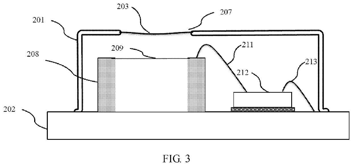
[0057]FIG. 3 shows a schematic diagram of a MEMS microphone device according to a third embodiment of the present invention, in which a acoustic port 207 is provided in the cover 201.

[0058]As shown in FIG. 3, the cover 201 is mounted on the substrate 202. The MEMS microphone element 208 with a diaphragm 209 is placed on the substrate 202 and is encapsulated by the cover 201 and the substrate 202.

[0059]A acoustic port 207 is provided in the cover 201. A compliant membrane 203 is provided to seal the acoustic port 207. The membrane 203 has a mechanical stiffness lower than that of the diaphragm 209 of the MEMS microphone element 208.

[0060]The description for repetitive parts in FIG. 3 are omitted.

[0061]In the embodiments of the present invention, the prior art filter with mesh holes can be omitted. Ho...


PUM


Abstract

An MEMS microphone device and an electronics apparatus are provided. The MEMS microphone device comprises: a substrate; a MEMS microphone element placed on the substrate; a cover encapsulating the MEMS microphone element together with the substrate; and an acoustic port for the MEMS microphone element, wherein a compliant membrane is provided to seal the acoustic port, and the membrane has a mechanical stiffness lower than that of the diaphragm of the MEMS microphone element.

Description

FIELD OF THE INVENTION[0001]The present invention relates to the field of MEMS microphone, and more specifically, to a MEMS microphone device and an electronics apparatus.BACKGROUND OF THE INVENTION[0002]A Micro-Electro-Mechanical System, or MEMS, is a technology that in its most general form can be defined as miniaturized mechanical and electro-mechanical elements (i.e., devices and structures) that are made using the techniques of micro-fabrication. A MEMS microphone element is a microphone made by the MEMS technology. A MEMS microphone element can be first manufactured and then it is encapsulated into a MEMS microphone device on a substrate. The MEMS microphone device can further be assembled into an electronics apparatus such as a mobile phone, a pad, a laptop and so on.[0003]Because of the small size of the MEMS microphone element, the environment of manufacturing will influence the performance of an electronics apparatus which has a MEMS microphone device.[0004]Generally, a ME...

Claims


Application Information

Patent Timeline
IPC IPC(8): B81B7/00H04R19/04
CPCH04R19/04H04R2307/027H04R2307/023B81B2201/0257H04R2307/025B81B7/0061H04R2201/003H04R1/086H04R19/005H04R2207/00
Inventor ZOU, QUANBO
Owner WEIFANG GOERTEK MICROELECTRONICS CO LTD
Learn More