
Snow blower

a technology for snow blowers and shovels, which is applied in the direction of machine/engines, vehicle cleaning, liquid fuel engines, etc., can solve the problems of cumbersome users with limited physical strength, equipment is difficult to maneuver, and the use of shovels generates undesired stresses on the lower back portion of users

Inactive Publication Date: 2020-02-06
NKURUNZIZA DIDIER
View PDF0 Cites 1 Cited by
  • Summary
  • Abstract
  • Description
  • Claims
  • Application Information

AI Technical Summary

Benefits of technology

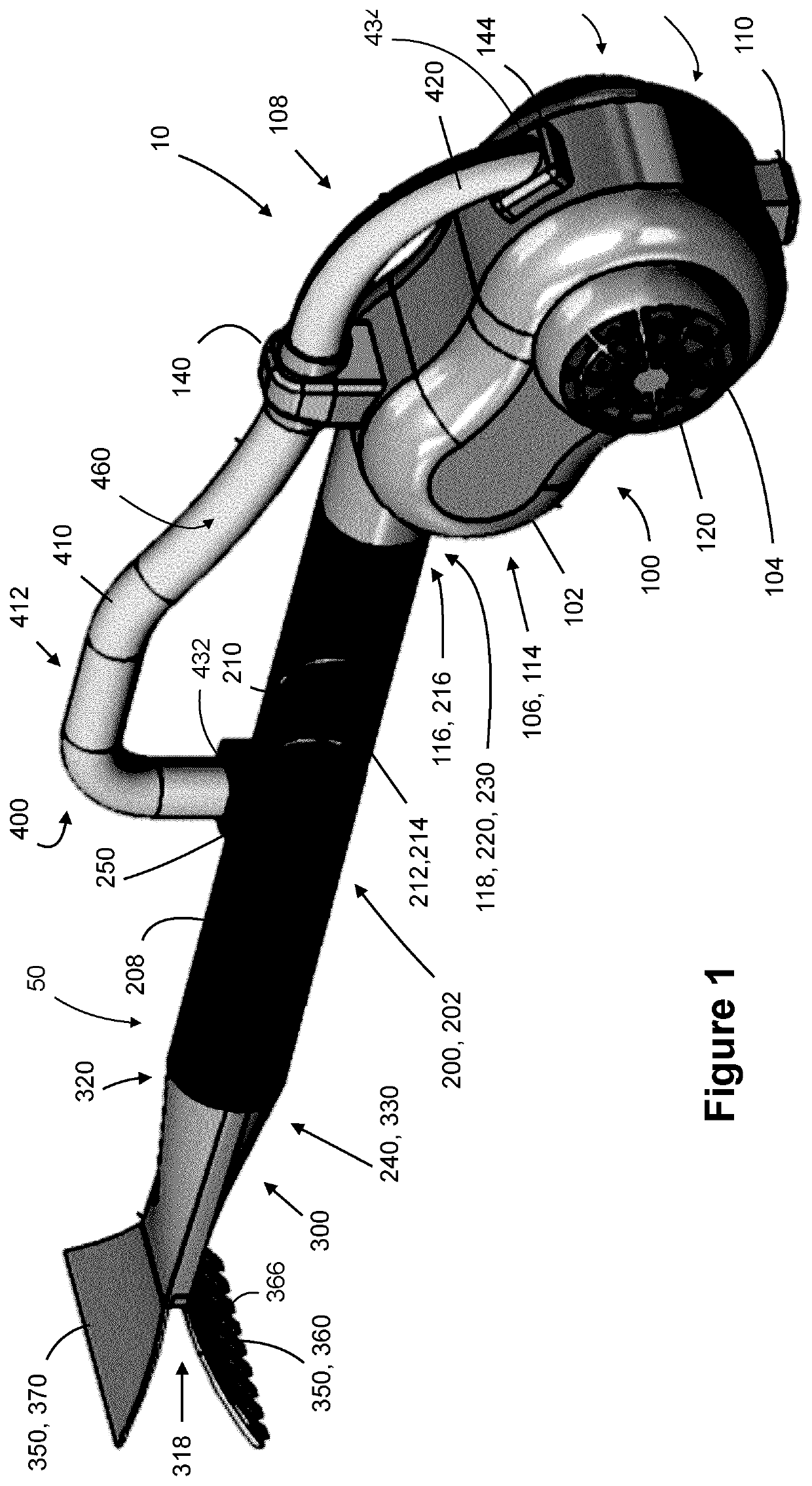
The snow blower described in this patent is a device used to remove snow and ice from surfaces. It includes an intake port, a conduit with an interior wall, a power source, an electric circuit, an electric blower, and a heating coil. The electric blower draws air through the intake port and exhausts it heated by the heating coil through the discharge port. The snow blower also includes a nozzle with a pair of blades that guide the air exhaust. The device can be powered by a battery and has a handle for easy handling. The technical effect of this snow blower is to provide an effective and efficient tool for removing snow and ice from surfaces.

Problems solved by technology

Use of a shovel generates undesired stresses onto a lower back portion of the user and causes fatigue when large amounts of snow must be removed.
However, such equipment is difficult to maneuver and may be cumbersome for users with limited physical strength.
Furthermore, traditional snow blowers are disadvantaged in cleaning elevated surfaces such as steps and porches.
Additionally, the use of a shovel or traditional snow blower equipment fails to completely remove snow and ice build-up from the ground surface.
However, none of these solutions is well adapted to a variety of conditions, including de-icing small areas, removing snow and de-ice of a car for instance.

Method used


Image

  • Snow blower
  • Snow blower
  • Snow blower

Examples


Embodiment Construction

[0035]It will be noted that, for the sake of clarity and understanding, spatial references such as top, bottom, front and back are used for teaching purpose only and do not limit the use or structure of the embodiments of snow blower more than limitation regarding the relative components, relative locations and configurations of the different parts of the embodiments of snow blower herein described.

[0036]It will be noted that the terms upstream and downstream are further used to identify components, component parts and locations, these terms referring to the flow of air within the snow blower.

[0037]Furthermore, it will be noted that snow and ice are used as example of materials to be removed, based on its characteristics. However, the embodiments of snow blower may be used in relation with other material sharing at least some of the characteristics of snow and ice without departing from the intended scope of the present teaching.

[0038]Referring now to the drawings, and more particul...


PUM


Abstract

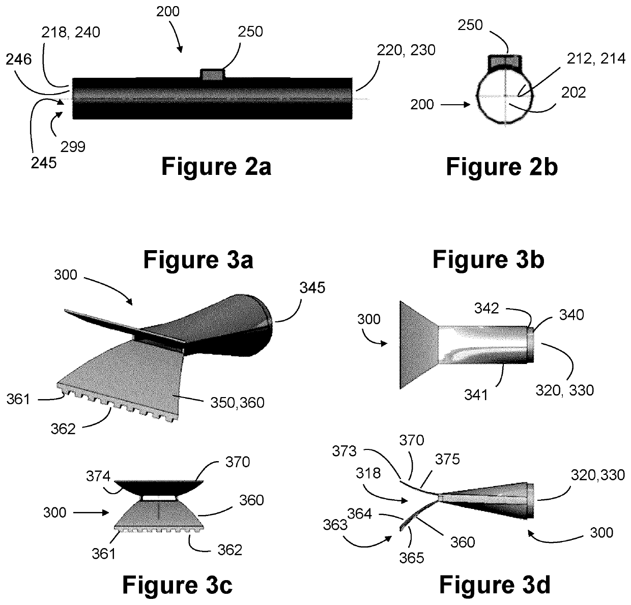
A snow blower (10) for blowing snow off a surface. The snow blower (10) comprises a body (50) comprising an intake port (120); a discharge port (318); and a conduit (202) having an interior wall (212). The conduit (202) is fluidly connecting the intake port (120) to the discharge port (318). The snow blower (10) further comprises an electric circuit (114) housed by the body (50) and connected to a power source; an electric blower (104) housed by the body (50) and powered by the electric circuit (114) for drawing air from the intake port (120); and a heating coil (210) electrically connected to the electric circuit (114) and extending along a portion of the interior wall (212). The air is forced through the conduit (202), heated by the heating coil (210) and exhausted at the discharge port (318) to blow snow off the surface.

Description

CROSS-REFERENCE TO RELATED APPLICATION[0001]This application claims priority from U.S. patent provisional application 62 / 601,439 filed Mar. 22, 2017 and from U.S. patent provisional application 62 / 522,850 filed Jun. 21, 2017, the specifications of which are hereby incorporated herein by reference in its entirety.BACKGROUND(a) Field[0002]The present disclosure relates to the field of vehicle maintenance accessories, but more particularly to vehicle snow blowers.(b) Related Prior Art[0003]As is generally well known, snow removal is accomplished either by using a shovel or a power operated ground engaging snow blower. Use of a shovel generates undesired stresses onto a lower back portion of the user and causes fatigue when large amounts of snow must be removed.[0004]Use of a traditional ground engaging powered snow blower equipment alleviates the problem of lower back stresses and user fatigue. However, such equipment is difficult to maneuver and may be cumbersome for users with limite...

Claims


Application Information

Patent Timeline
Patent Type & Authority Applications(United States)
IPC IPC(8): E01H5/02B60S3/04
CPCE01H5/02B60S3/045E01H5/098B60S3/047H05B1/0236H05B1/0244H05B3/56H05B2203/022H05B2214/02E01H5/061E01H5/106E01H1/12E01H1/0818F04D25/084F04D29/4226F04D29/545F05D2250/52F04D29/701F04D29/582F04D25/0673
Inventor NKURUNZIZA, DIDIER
Owner NKURUNZIZA DIDIER
Learn More