Parking lock module for actuating a parking lock in a motor vehicle

a technology for parking locks and modules, which is applied in the direction of fluid-pressure actuators, gearing elements, belts/chains/gearrings, etc., can solve the problems of large space, large amount of space, and large structural space required for the detent unit of the known parking lock module, etc., and achieves the effect of reducing the installation space of the parking lock module on/in the transmission housing, and reducing the installation spa

Active Publication Date: 2020-02-06
FTE AUTOMOTIVE GMBH & CO KG
View PDF0 Cites 1 Cited by
  • Summary
  • Abstract
  • Description
  • Claims
  • Application Information

AI Technical Summary

Benefits of technology

This patent describes an arresting device for a parking lock module that is simpler and less expensive than previous designs. The detent element is guided displaceably along the feed axis, eliminating the need for voluminous and cumbersome detent lever and lever arms. The invention requires less structural space, resulting in a compact and efficient arresting device. The spring for preloading the detent element can be integrated in the electromagnetic actuator, further reducing the size and complexity of the arresting device. Overall, the invention simplifies the design and installation process and reduces costs while maintaining functionality.

Problems solved by technology

A disadvantage of this prior art can be seen in particular in the fact that the design of the detent unit with a multiplicity of parts, and the installation thereof in and / or on the parking module, is associated with considerable outlay, which is undesirable in the context of mass production.
Furthermore, the detent unit of the known parking lock module requires a relatively large structural space, which is to be attributed in particular to the fact that the detent lever, in order to provide sufficiently large lever arms and stop surfaces, itself takes up a relatively large amount of space, and the restoring spring, the electromagnetic actuator and the hydraulic actuator engage on the detent lever at points which are spaced apart from one another to a correspondingly great extent.
The installation space available for the parking lock module on / in the transmission housing is however generally very constricted.

Method used


Image

  • Parking lock module for actuating a parking lock in a motor vehicle
  • Parking lock module for actuating a parking lock in a motor vehicle
  • Parking lock module for actuating a parking lock in a motor vehicle

Examples


Embodiment Construction

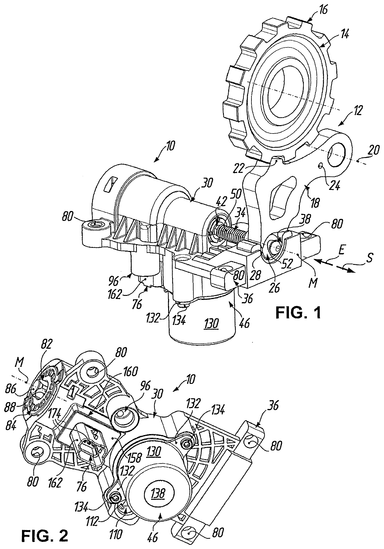
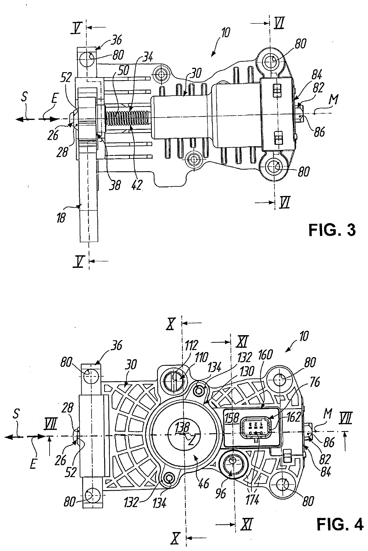
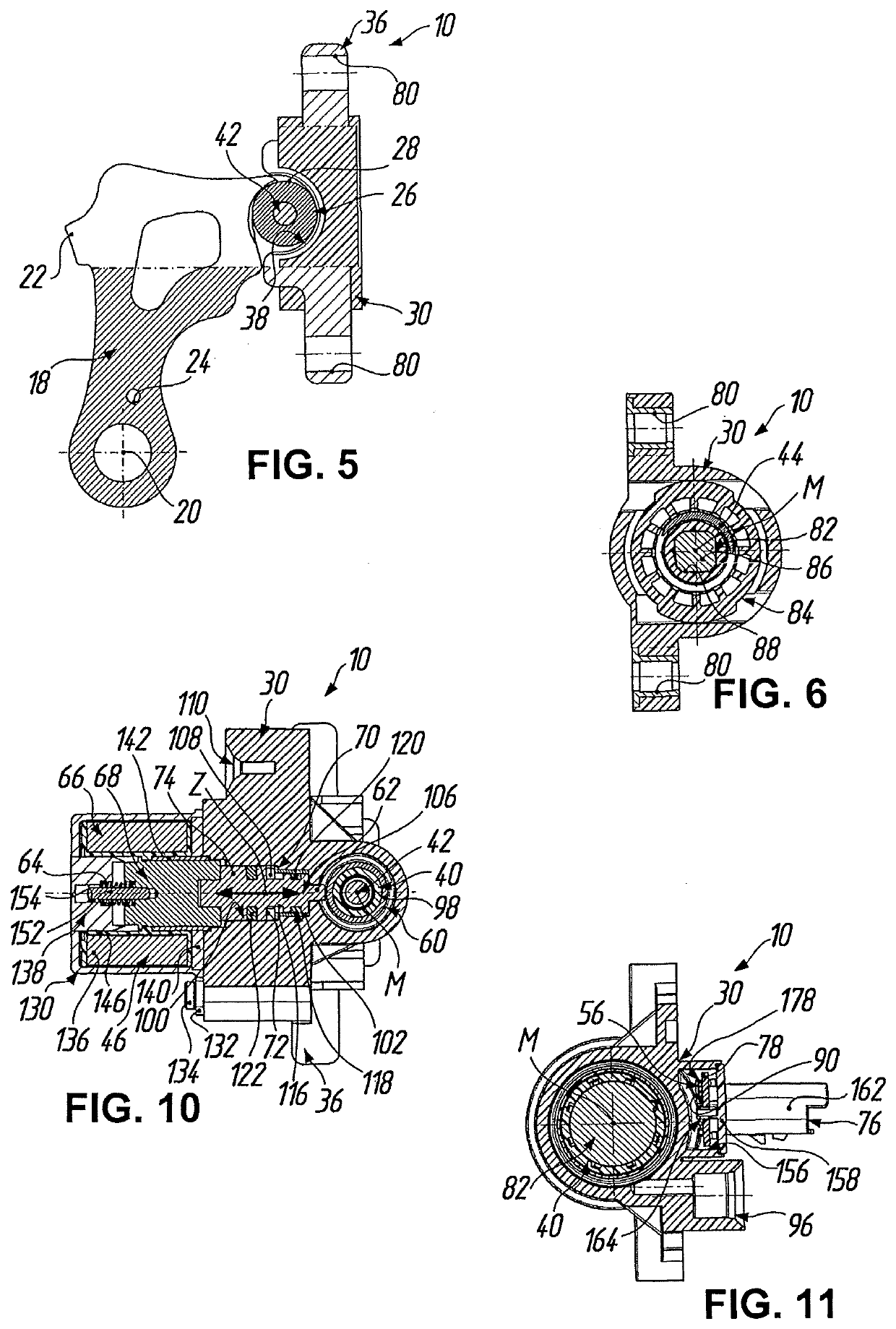
[0046]In the figures, the reference designation 10 is used generally to denote a parking lock module for actuating a parking lock 12 in a motor vehicle. As per FIG. 1, the parking lock 12 has, in a manner known per se, a parking lock wheel 14 which is arranged rotationally conjointly and axially fixedly on a transmission shaft (not illustrated) of a motor vehicle transmission and which has, on the outer circumference, a toothing 16. For the arresting of the drive train of the motor vehicle with form-fitting action, the parking lock 12 furthermore has a pawl 18 (shown only in FIGS. 1, 3 and 5) which is articulated on a transmission housing (not shown here) so as to be pivotable about a pivot axis 20. The pawl 18 has a locking tooth 22 which, during a pivoting of the pawl 18 about the pivot axis 20, can engage in form-fitting fashion with the toothing 16 of the parking lock wheel 14. The reference designation 24 indicates a bore in the pawl 18, which is engaged on by a restoring sprin...


PUM


Abstract

A parking lock module has a housing, in which, for the actuation of a parking lock, a positioning member movable from a locking position into an unlocking position and vice versa. The positioning member is selectively fixable relative to the housing with an arresting device, which has a detent contour fixed to the positioning member and has a detent element on the housing. The detent element is movable from an arresting position into a release position, and vice versa. The detent element is preloaded into the arresting position with a spring and is actively movable into the release position with a fluidic actuator with a pressurizable effective surface. The detent element can be formed as a piston guided displaceably along a feed axis and which forms the pressurizable effective surface of the fluidic actuator.

Description

TECHNICAL FIELD[0001]The invention relates to a parking lock module for actuating a parking lock in a motor vehicle, as per the preamble of patent claim 1. In particular, the invention relates to a parking lock module such as has recently found widespread use in the automotive industry in motor vehicles with hybrid transmissions and modern transmissions with an automatic nature (automated manual transmissions).PRIOR ART[0002]Parking locks are required in particular when a self-locking action of the drive (engine) cannot be utilized to hold the motor vehicle stationary. Locking of the drive train is then generally realized by means of a parking lock wheel which is arranged rotationally conjointly on an output shaft of the transmission and which has a toothing and which, by means of a parking lock pawl mounted pivotably on a parallel axle, can be locked in form-fitting fashion at the toothing, wherein the parking lock pawl must be pivoted counter to the force of a restoring spring whi...

Claims


Application Information

Patent Timeline
Patent Type & Authority Applications(United States)
IPC IPC(8): F16H63/34F15B15/14
CPCF15B15/14F16H63/3483F16H63/3475F16H63/3425F16H63/38F16H63/3491F16H63/3416F16H63/3023F16H63/304
Inventor GEBERT, STEFANSELCH, STEVESCHWIPP, ANDREAS
Owner FTE AUTOMOTIVE GMBH & CO KG
Why Eureka
Try Eureka