Fiber optic Fabry-Perot interferometer and associated methods

a fiber optic fabryperot and interferometer technology, applied in the field of optical sensors, can solve the problems of difficult automation of processes, high production costs, and high production costs, and achieve the effects of less production costs, less timely processes, and easy automation

Inactive Publication Date: 2005-05-03
HARRIS CORP +1
View PDF7 Cites 20 Cited by
  • Summary
  • Abstract
  • Description
  • Claims
  • Application Information

AI Technical Summary

Benefits of technology

[0006]In view of the foregoing background, it is therefore a feature of the invention to provide a fiber optic Fabry-Perot interferometric sensor which is less expensive to produce via an easily automated and less timely process.

Problems solved by technology

This is typically an expensive and timely process that involves either an active alignment or a passive alignment.
These processes are also difficult to automate.

Method used


Image

  • Fiber optic Fabry-Perot interferometer and associated methods
  • Fiber optic Fabry-Perot interferometer and associated methods
  • Fiber optic Fabry-Perot interferometer and associated methods

Examples


Embodiment Construction

[0016]The present invention will now be described more fully hereinafter with reference to the accompanying drawings, in which preferred embodiments of the invention are shown. This invention may, however, be embodied in many different forms and should not be construed as limited to the embodiments set forth herein. Rather, these embodiments are provided so that this disclosure will be thorough and complete, and will fully convey the scope of the invention to those skilled in the art. Like numbers refer to like elements throughout. The dimensions of layers and regions may be exaggerated in the figures for clarity.

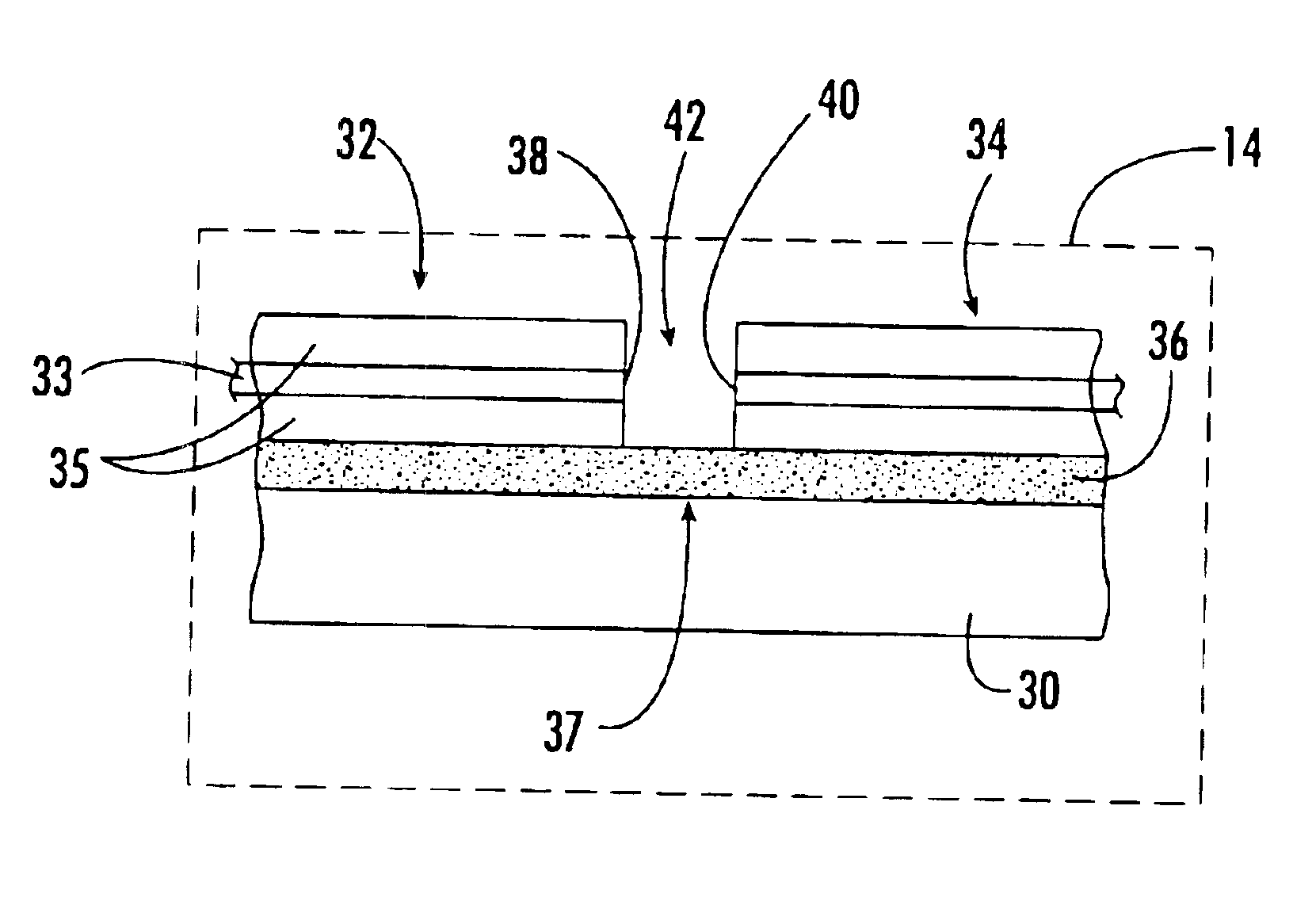
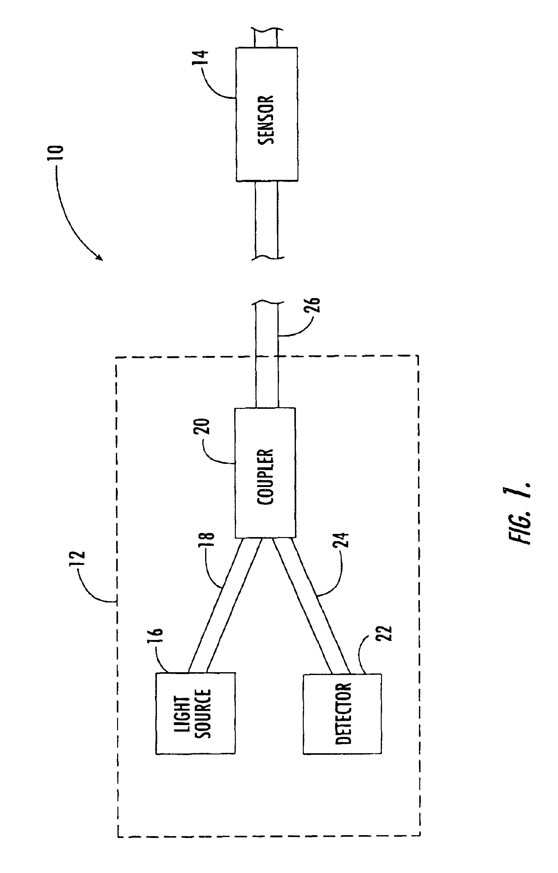
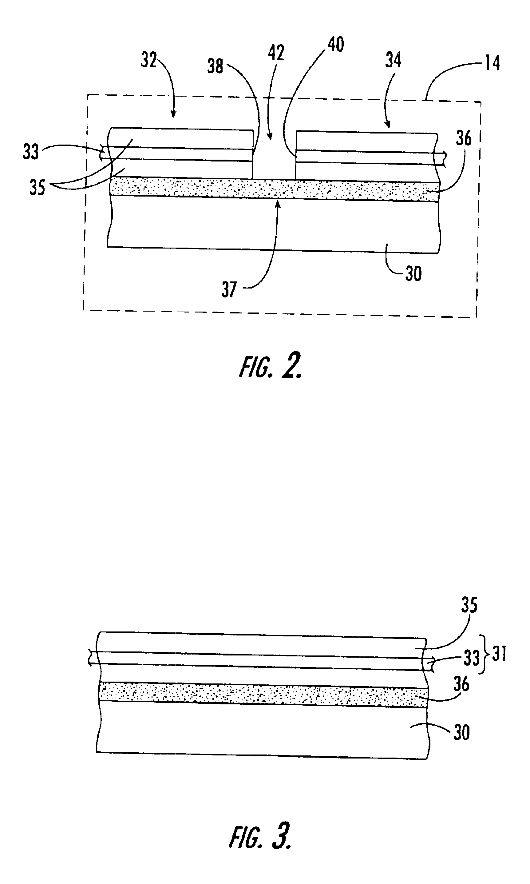
[0017]Referring to FIGS. 1 and 2, a fiber-optic Fabry-Perot interferometric (FFPI) sensor system 10 will now be described. The system 10 includes a control and signal processor 12 coupled to a FFPI sensor 14 via fiber optic cable 26. The sensor 14 can be located kilometers away from the processor 12, and requires no electrical power. The processor 12 includes light source 1...


PUM

PropertyMeasurementUnit
coefficient of thermal expansionaaaaaaaaaa
piezoelectricaaaaaaaaaa
flexibleaaaaaaaaaa

Abstract

The method for making the fiber optic Fabry-Perot sensor includes securing an optical fiber to a substrate, and forming at least one gap in the optical fiber after the optical fiber is secured to the substrate to define at least one pair of self-aligned opposing spaced apart optical fiber end faces for the Fabry-Perot sensor. Preferably, an adhesive directly secures the at least one pair of optical fiber portions to the substrate. The opposing spaced apart optical fiber end faces are self-aligned because the pair of optical fiber end portions are formed from a single fiber which has been directly secured to the substrate. Also, each of the self-aligned spaced apart optical fiber end faces may be substantially rounded due to an electrical discharge used to form the gap. This results in integral lenses being formed as the end faces of the fiber portions.

Description

FIELD OF THE INVENTION[0001]The present invention relates to optical sensors, and more particularly, to fiber optic fabry-perot interferometers.BACKGROUND OF THE INVENTION[0002]The Fabry-Perot Interferometer (FPI) is described by C. Fabry and A. Perot in 1897 (Ann. Chem. Phys., 12:459-501) and is widely used in a variety of applications of optical systems. The basic structure and operation of the FPI sensor is well-known in the art and is described in many physics and optics texts. This interferometer includes an optical cavity formed between two typically reflecting, low-loss, partially transmitting mirrors.[0003]The use of optical fibers allows for the manufacture of extremely compact and economic sensors known as Fiber-optic Fabry-Perot interferometric (FFPI) sensors. Ends of optical fiber portions form partially reflective surfaces with the cavity or gap therebetween. Changing the distance between optic fiber ends in the cavity or stretching an optical fiber in the cavity change...

Claims


Application Information

Patent Timeline
Patent Type & Authority Patents(United States)
IPC IPC(8): G01B9/02G01J3/12G01J3/26G01J3/02G01J3/00G02B6/00G01J5/08G02B6/26
CPCG01D5/264G01D5/266G01D5/268G01J3/0218G01J3/26G01J3/02G02B6/0001
Inventor RUMPF, RAYMOND C.MURSHID, SYED H.
Owner HARRIS CORP
Why Eureka
Try Eureka