Low Mixing Ventilation Jet

a technology of low-mixing and ventilation jets, which is applied in ventilation systems, lighting and heating apparatus, heating types, etc., can solve the problems of large energy costs of volumetric flow, and achieve the effect of less expensive production and reduced jet mixing degr

Inactive Publication Date: 2011-02-17
SYRACUSE UNIVERSITY
View PDF4 Cites 22 Cited by
  • Summary
  • Abstract
  • Description
  • Claims
  • Application Information

AI Technical Summary

Benefits of technology

[0015]The present invention relates to ventilation (see Definitions section) nozzles and new applications for ventilation nozzles. The ventilation nozzles of the present invention provide (at least) two airflows wherein on outer airflow (at least partially) surrounds an inner airflow. Preferably, the outer airflow has different temperature, humidity and / or cleaned air (see Definitions section) than the inner airflow, and is therefore less expensive to produce than the inner airflow. The outer airflow decreases the degree of jet mixing and entrainment of the inner airflow.

Problems solved by technology

This large volumetric flow has commensurately large energy costs associated with: (i) thermal conditioning; (ii) filtering / cleaning and / or (iii) moving the air.

Method used


Image

  • Low Mixing Ventilation Jet
  • Low Mixing Ventilation Jet
  • Low Mixing Ventilation Jet

Examples


Embodiment Construction

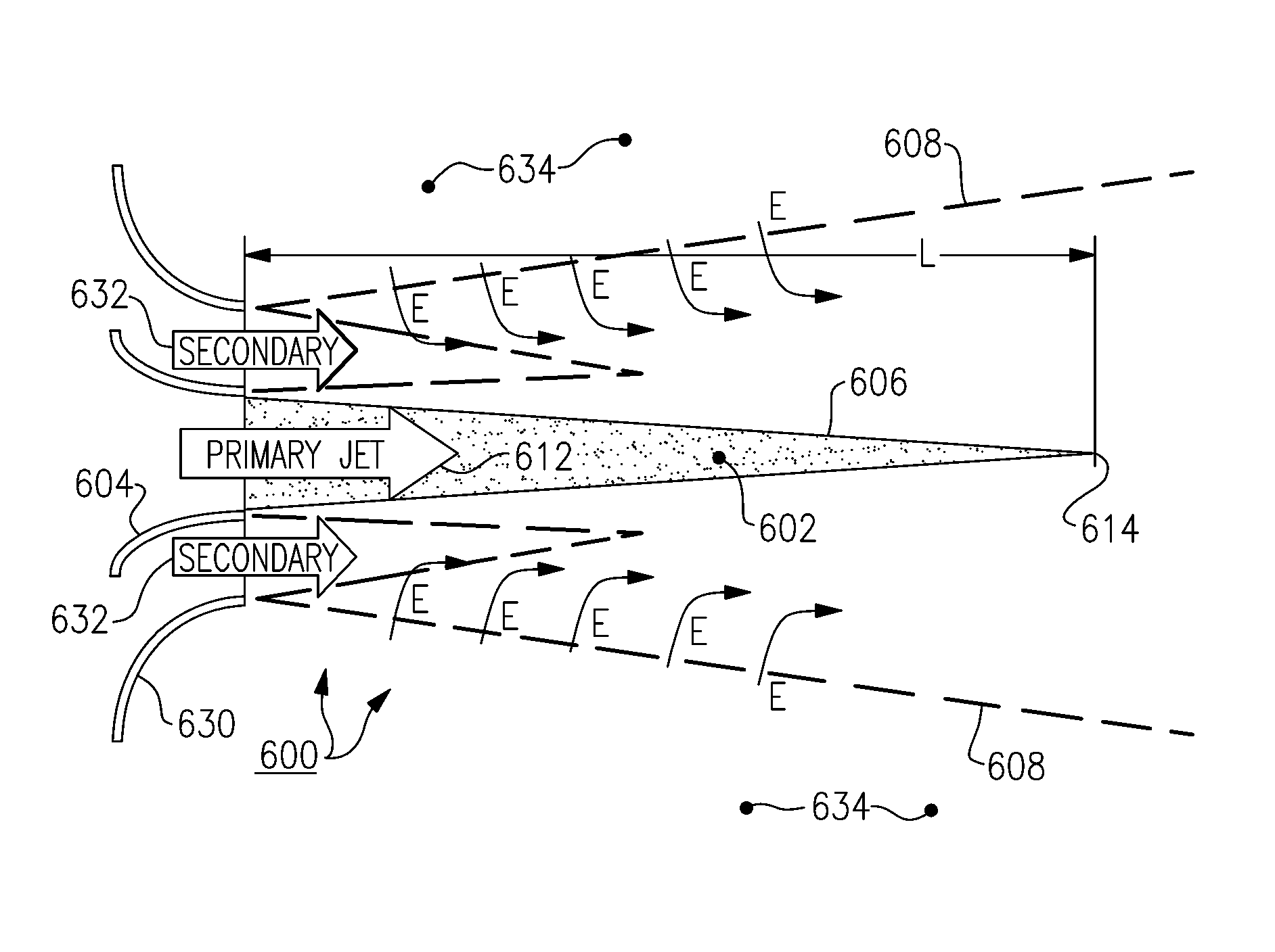
[0046]Before discussing specific embodiments, the theoretical basis of the present invention will first be discussed. An air jet issuing from a nozzle into still or co-flowing air at a different velocity experiences shear at its boundary. For sufficiently high jet Reynolds number, turbulence is produced in the shear layer between the jet and its surrounding medium, and the resulting turbulent eddies greatly enhance the transport of momentum, energy and species in this shear layer. As a result, the potential core of the jet gradually erodes due to the entrainment of low momentum fluid from the surrounding medium into the jet. This turbulent transport also enhances the entrainment of species from the surrounding medium into the jet's mixing zone. It has been recognized that the turbulent momentum diffusivity in such free shear layers is proportional to the width of the shear layer and the difference between the jet centerline velocity and the velocity of the surrounding medium (zero f...


PUM


Abstract

A ventilation system with hardware to direct two independent airflows, wherein an outer airflow (at least partially) surrounds the an inner airflow. Preferably the inner and outer airflows come from different sources such that the air of the inner airflow has higher associated costs than the air of the outer airflow. For example, the inner airflow may be more cleaned and/or more thermally conditioned than the outer airflow. The inner airflow may have a different velocity than the outer airflow. Preferably, the ventilation system is a PVD, but other applications are also contemplated, such as: (i) spot-cooling; (ii) air curtains (for example for a refrigerated food section or case in a market); (iii) medical devices (for example, oxygen supply devices, “blankets” of thermally conditioned and/or cleaned air for infants, patients in surgery or burn victims, shields of cleaned air for protection against microbes for patients with compromised immune systems); (iv) personal humidifiers; (v) personal dehumidifiers; (vi) thermal and/or humidity control for plant or animal enclosures; and/or (vii) any other ventilation system for controlling at least one type of air characteristic (see Definitions section).

Description

BACKGROUND OF THE INVENTION[0001]1. Field of the Invention[0002]The present invention relates to ventilation systems and more particularly to ventilation systems for providing cleaned air (see Definitions section), thermally conditioned air (see Definitions section) and / or humidity-controlled air to a particular zone.[0003]2. Description of the Related Art[0004]It is often desirable to provide cleaned, thermally conditioned and / or humidity controlled air to a particular zone. As one example of this, research indicates that providing building occupants with devices to control the flow of air in their immediate environments to their personal preferences can enhance their satisfaction and work performance. A couple examples of such research are set forth in: (i) Arens, E., T. Xu, K. Miura, Z. Hui, M. Fountain, and F. Bauman (1998), “A study of occupant cooling by personally controlled air movement”, Energy and Buildings, vol. 27, pp. 45-49 (1998); (ii) Melikov, A. K., R. Cermak and M. ...

Claims


Application Information

Patent Timeline
Patent Type & Authority Applications(United States)
IPC IPC(8): F24F13/06
CPCF24F13/04F24F2221/38F24F13/06
Inventor KHALIFA, H. EZZATGLAUSER, MARK
Owner SYRACUSE UNIVERSITY
Why Eureka
Try Eureka