Centralized label-based software defined network

a software defined network and label technology, applied in the field of central label-based label-based software defined network, can solve the problems of limiting the number of network hops, data centers facing bandwidth requirements and congestion, and limiting the applicability of this approach

Active Publication Date: 2020-02-06
META PLATFORMS INC
View PDF0 Cites 10 Cited by
  • Summary
  • Abstract
  • Description
  • Claims
  • Application Information

AI Technical Summary

Problems solved by technology

Like many networks, the data centers face bandwidth requirements and congestion, particularly with the increase in popularity of photos and videos.
However, a hardware limit on the number of network hops that can be encoded in the packet header typically limits the applicability of this approach.

Method used


Image

  • Centralized label-based software defined network
  • Centralized label-based software defined network
  • Centralized label-based software defined network

Examples


Embodiment Construction

[0010]The invention can be implemented in numerous ways, including as a process; an apparatus; a system; a composition of matter; a computer program product embodied on a computer readable storage medium; and / or a processor, such as a processor configured to execute instructions stored on and / or provided by a memory coupled to the processor. In this specification, these implementations, or any other form that the invention may take, may be referred to as techniques. In general, the order of the steps of disclosed processes may be altered within the scope of the invention. Unless stated otherwise, a component such as a processor or a memory described as being configured to perform a task may be implemented as a general component that is temporarily configured to perform the task at a given time or a specific component that is manufactured to perform the task. As used herein, the term ‘processor’ refers to one or more devices, circuits, and / or processing cores configured to process da...


PUM


Abstract

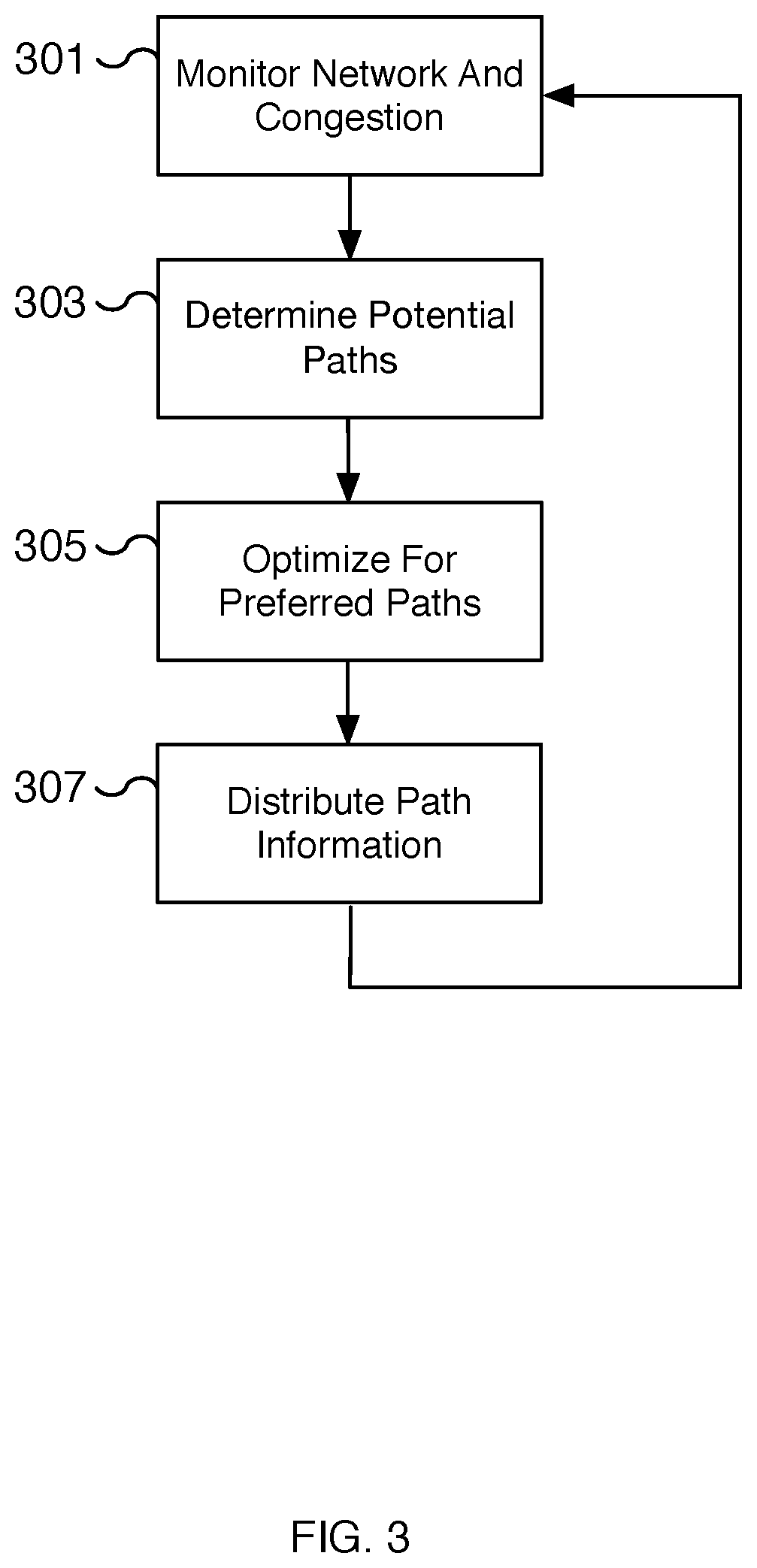
A specification of network paths between a group of computer network routers is received and possible route paths between routers of the group of computer network routers are determined. A unique identifier is assigned to each route path of the possible route paths. A preferred route path of network traffic between a source computer network router and a destination computer network router among the group of computer network routers is determined and the unique identifier assigned to the preferred route path is identified. A specification of the identified unique identifier and a specification of at least a portion of the preferred route path that corresponds to the identified unique identifier are provided to at least the computer network routers in the preferred route path.

Description

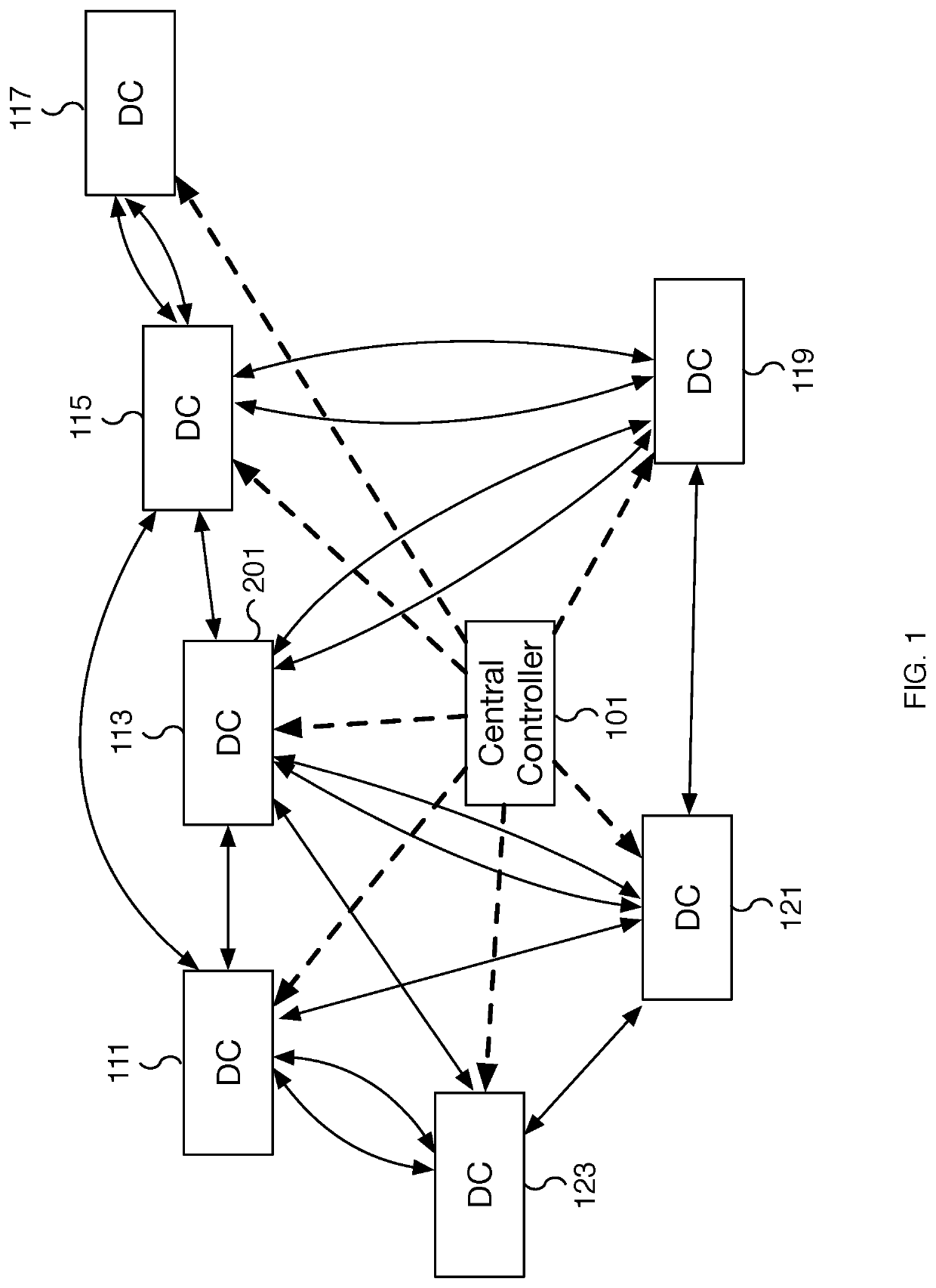
BACKGROUND OF THE INVENTION[0001]Data centers that host web applications are typically interconnected. Like many networks, the data centers face bandwidth requirements and congestion, particularly with the increase in popularity of photos and videos. In some situations, additional data centers may be brought online and new network nodes and links are added to the network connecting data centers together. To expedite the delivery of data, the routes between the data centers are monitored and typically the shortest path between source and destination nodes is selected. As the network topology grows, the path taken to reach certain destinations from a particular source location may begin to reach the limit of the network forwarding hardware. Moreover, at times, the shortest path does not correspond to the fastest path in terms of latency. One traditional approach is to create an explicit route that is specified in the packet headers to indicate a more optimal path. However, a hardware ...

Claims


Application Information

Patent Timeline
Patent Type & Authority Applications(United States)
IPC IPC(8): H04L12/723H04L12/26H04L45/50H04L45/02
CPCH04L45/50H04L43/0882H04L43/0811H04L45/125
Inventor KWOK, HENRYSU, SONGQIAOLAPUKHOV, PETR V.
Owner META PLATFORMS INC
Why Eureka
Try Eureka