Sound Generator

a generator and sound technology, applied in the field of electroacoustic components, can solve the problems of poor structure stability, low reliability, and loss of effectiveness

Active Publication Date: 2020-02-06
AAC TECH PTE LTD
View PDF2 Cites 0 Cited by
  • Summary
  • Abstract
  • Description
  • Claims
  • Application Information

AI Technical Summary

Problems solved by technology

When the sound generator drops, the structure is easy to have the problem that the glue loses effectiveness, which causes the disconnection between the pole plate and magnet, and th...

Method used


Image

  • Sound Generator
  • Sound Generator

Examples


Embodiment Construction

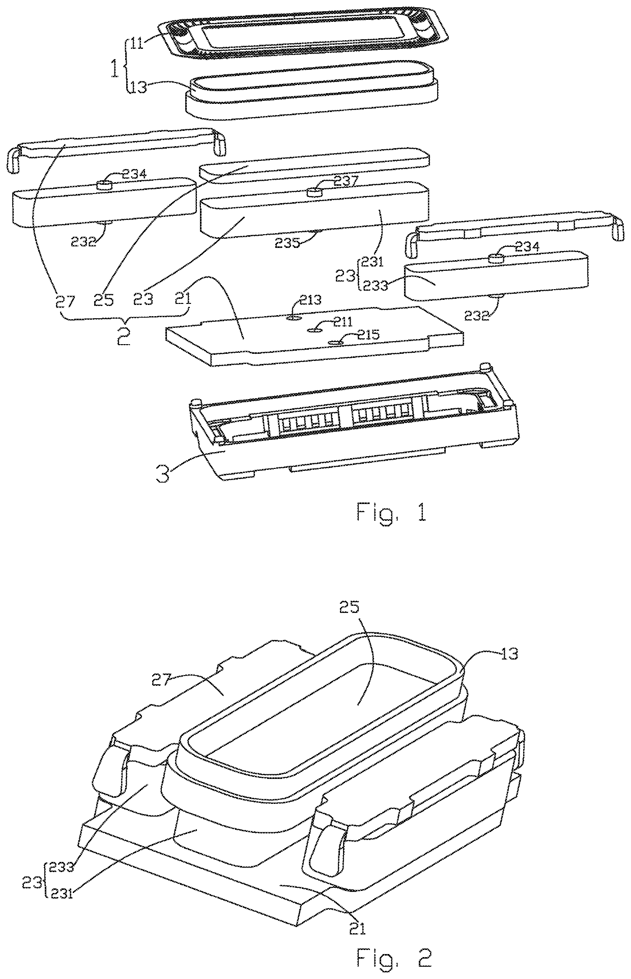
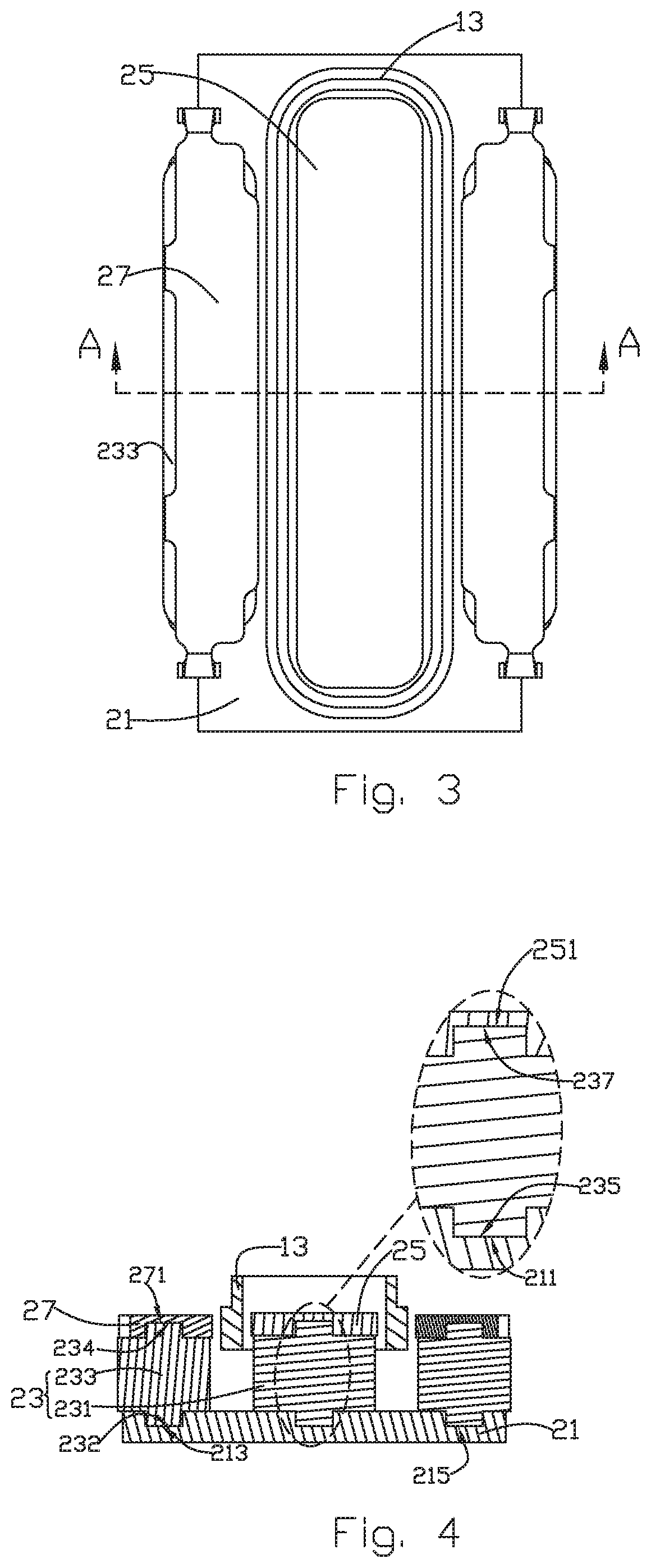
[0009]The present disclosure will hereinafter be described in detail with reference to exemplary embodiment. To make the technical problems to be solved, technical solutions and beneficial effects of the present disclosure more apparent, the present disclosure is described in further detail together with the figures and the embodiment. It should be understood the specific embodiment described hereby are only to explain the disclosure, not intended to limit the disclosure.

[0010]The following specific embodiment is provided to make the readers understand the contents of the present disclosure clearer and more thoroughly but not restrict the present disclosure, wherein, the upper, lower, left and right words indicating directions only refer to the position of the structure shown in the corresponding figure. The one near the center of the sound generator is defined inner side, and the one far from the center of the sound generator is defined the outer side.

[0011]As shown in FIGS. 1-3, t...


PUM


Abstract

The present invention provides a sound generator, including a magnetic circuit system having a magnet and a lower plate for carrying the magnet. The magnet includes a first surface opposite to the lower plate and a second surface opposite to the first surface. The first surface of the magnet protrudes to form a first bolt, the lower plate is provided with a lower plate jack matching with the first bolt, and the first bolt is inserted into the lower plate jack. The sound generator of the present disclosure improves the structural stability of the magnetic circuit system and is convenient for positioning.

Description

FIELD OF THE PRESENT DISCLOSURE[0001]The embodiments of the invention relate to the electroacoustic components, in particular to a sound generator used in a portable device.DESCRIPTION OF RELATED ART[0002]Sound generators, also called sound generators, are widely used in portable electronic devices such as mobile phones, laptops, etc. With the rapid development of these portable electronic devices, people have higher and higher requirements for the performance of the sound generators. In addition, with the thinning development of mobile phones, the quality requirements for the sound generators in the mobile phones are becoming higher and higher. The sound generator is a playing device of the voice function and therefore its internal magnetic circuit system directly influences the improvement of the acoustic performance of the product.[0003]In the sound generator of the related technology, the connection between the magnet and the lower plate, and the connection between the magnet an...

Claims


Application Information

Patent Timeline
IPC IPC(8): H04R9/02H02K1/06
CPCH04R9/025H02K1/06H02K41/0356
Inventor ZHANG, TONG
Owner AAC TECH PTE LTD
Why Eureka
Try Eureka