Hand exoskeleton force feedback system

a technology of exoskeleton and force feedback, which is applied in the direction of mechanical pattern conversion, program-controlled manipulators, instruments, etc., can solve the problems of inability of devices using computer vision to track hand motion, inability to generate correct hand models, and common disadvantages of computer vision devices

Active Publication Date: 2020-02-13
SHENZHEN DEXTA ROBOTICS CO LTD
View PDF8 Cites 7 Cited by
  • Summary
  • Abstract
  • Description
  • Claims
  • Application Information

AI Technical Summary

Benefits of technology

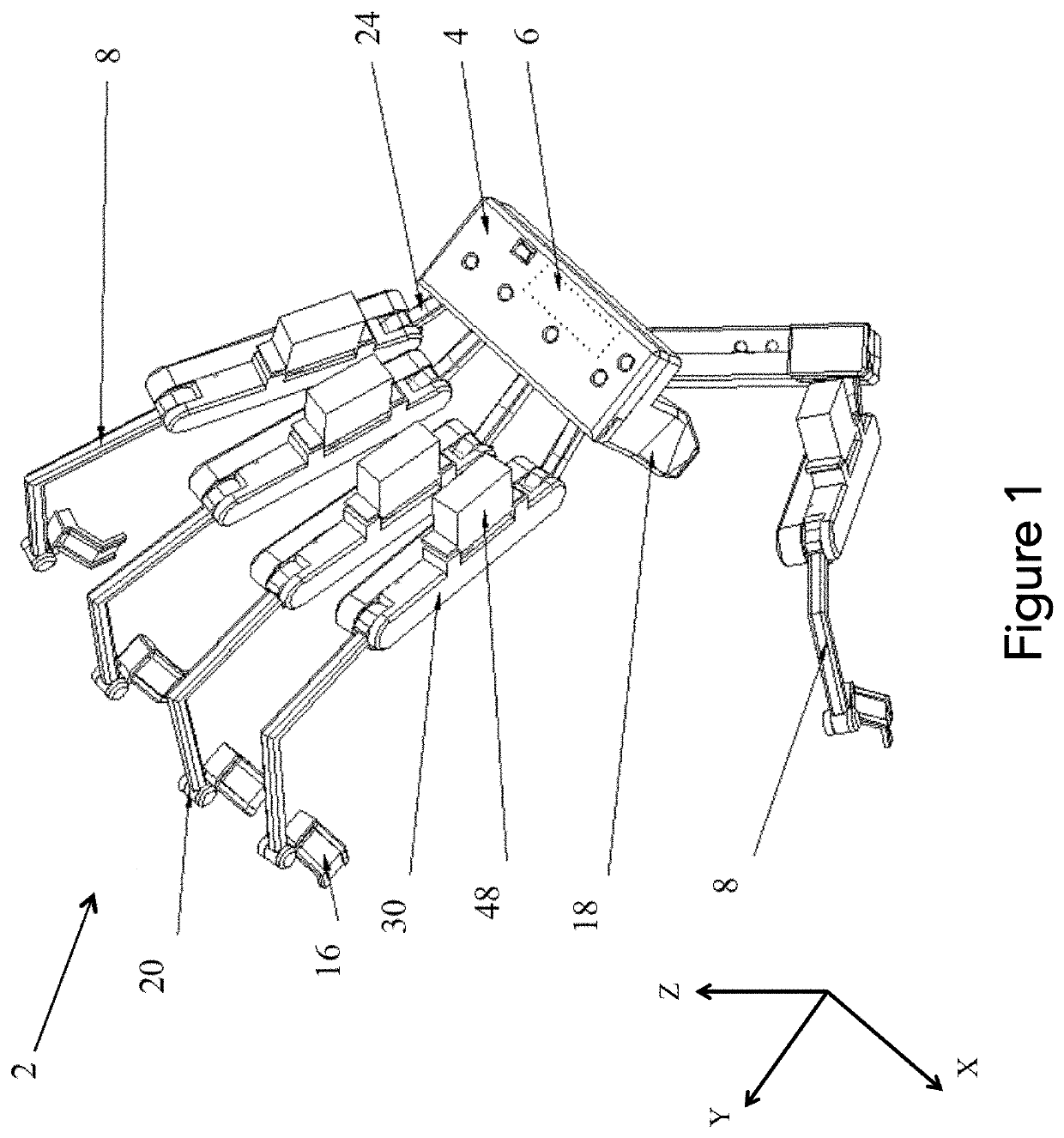
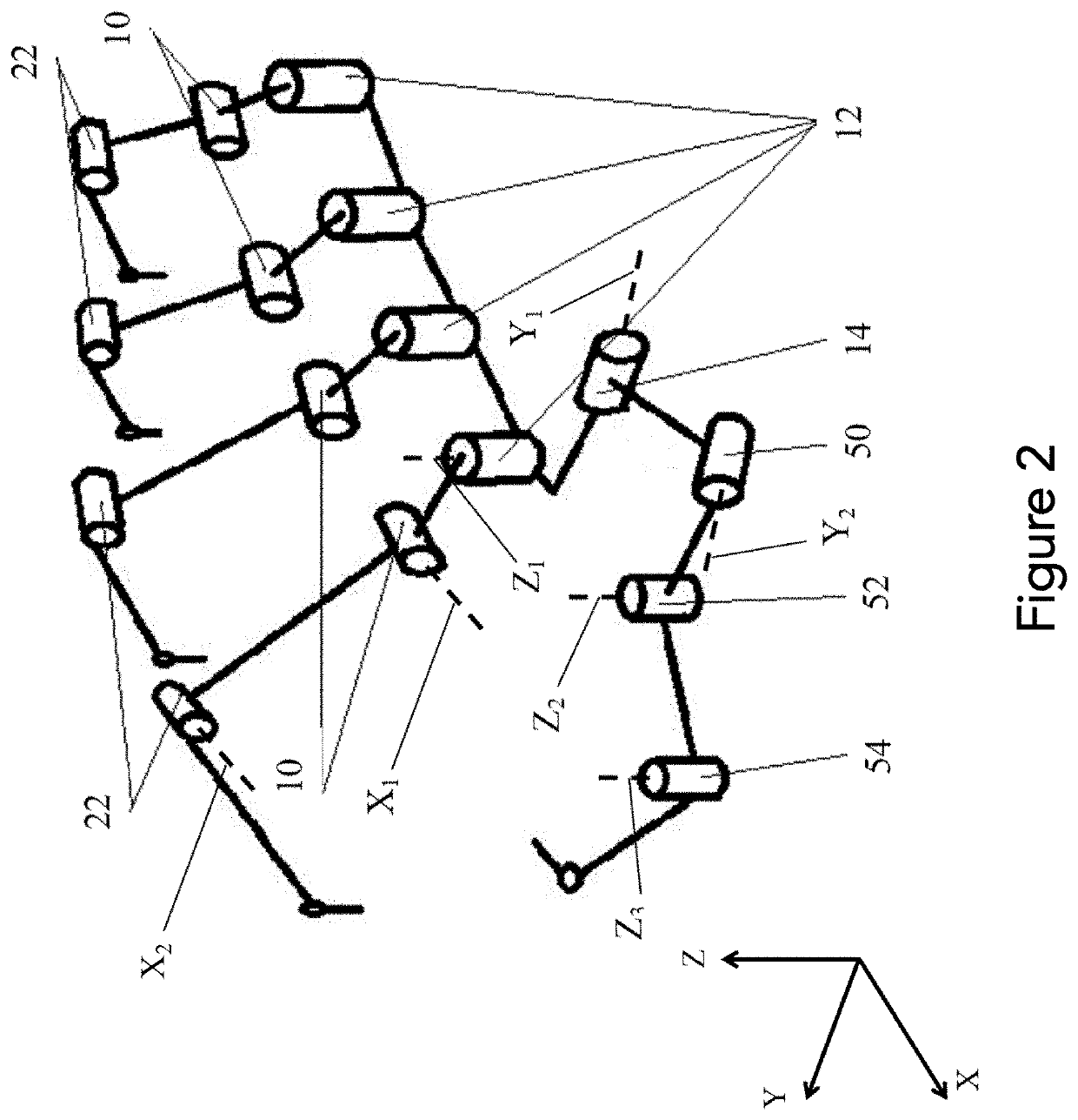
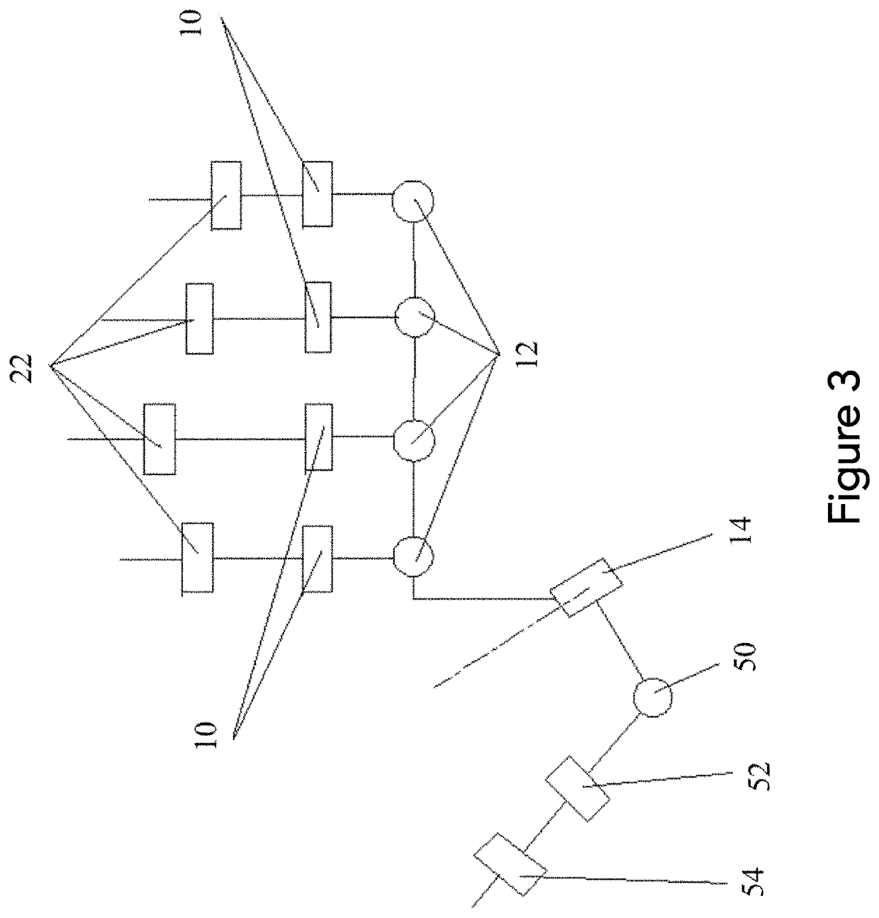
[0013]Some embodiments may include one or more of the following. The force feedback unit may be mechanically coupled to the base. The force feedback unit may be electronically coupled to the microcontroller. The force feedback unit may be a first force feedback unit, and the force feedback device may further comprise a second force feedback unit, a third force feedback unit, a fourth force feedback unit, and a fifth force feedback unit. Each of the first force feedback unit, second force feedback unit, third force feedback unit, fourth force feedback unit, and fifth force feedback unit correspond to the five fingers of a hand. The force feedback unit may be mechanically coupled to the base with a bar. The force feedback device may be configured to capture hand motion. The exoskeleton may be a motion capturing device. The exoskeleton may be configured to interface with a motion capturing device.
[0014]Several embodiments may include one or more of the following. The force feedback device may further comprise at least one finger cap. The force feedback unit may be mechanically coupled to the finger cap. The force feedback unit may be mechanically coupled to the finger cap with a profiled bar. The force feedback device may further comprise a rotation sensor. The microcontroller may be a first microcontroller; and may further comprise a second microcontroller.
[0015]Several embodiments may include one or more of the following. The force feedback unit is a side-locking mechanism. The side-locking mechanism may comprise a first profiled gear ring, an upper link bar, a second profiled gear ring, a lower link bar, a linear actuator slider module, a first profiled anti-shaped-gear, a second profiled anti-shaped-gear, and a worm gear. It should be appreciated that the li

Problems solved by technology

However, some disadvantages are commonly seen in devices that use computer vision to track the motion of the hand.
The ability of these devices to track hand motion is restricted due to the camera's limited monitoring scope and direction.
These devices are not capable of generating a correct hand model when a user's hand is out of the camera's monitoring scope.
Furthermore, an optical-capturing-based solution is unable to offer force feedback without incorporating an additional wearable device.
A disadvantage of the IMU device is the need to recalibrate the zero-offset each time the device is placed in a new magnetic environment, and that it loses accurate tracking when placed in a strong magnetic field.
Additionally, because this approach involves installing drivers on the back of the user's hand, implementing force feedback is more difficult.
However, this approach is not able to

Method used


Image

  • Hand exoskeleton force feedback system
  • Hand exoskeleton force feedback system
  • Hand exoskeleton force feedback system

Examples


Embodiment Construction

[0060]Although certain embodiments and examples are disclosed below, inventive subject matter extends beyond the specifically disclosed embodiments to other alternative embodiments and / or uses, and to modifications and equivalents thereof. Thus, the scope of the claims appended hereto is not limited by any of the particular embodiments described below. For example, in any method or process disclosed herein, the acts or operations of the method or process may be performed in any suitable sequence and are not necessarily limited to any particular disclosed sequence. Various operations may be described as multiple discrete operations in turn, in a manner that may be helpful in understanding certain embodiments; however, the order of description should not be construed to imply that these operations are order dependent. Additionally, the structures, systems, and / or devices described herein may be embodied as integrated components or as separate components.

[0061]For purposes of comparing...


PUM


Abstract

This disclosure includes a force feedback system. In some embodiments, the system includes a base, a microcontroller communicatively coupled to a computing device, a thumb force feedback unit, and four finger force feedback units. The thumb force feedback unit may be configured to capture thumb motion and provide force feedback according to input from the computing device. Additionally, each of the four finger force feedback units may be configured to capture finger motion and provide force feedback according to input from the computing device. In some embodiments, the system includes at least one vibrational actuator configured to produce a physical stimulus.

Description

CROSS-REFERENCE TO RELATED APPLICATIONS[0001]This application claims the benefit of and is a continuation-in-part of U.S. patent application Ser. No. 15 / 155,220; filed May 16, 2016; and entitled HAND EXOSKELETON FORCE FEEDBACK SYSTEM. The entire contents of U.S. patent application Ser. No. 15 / 155,220 are incorporated herein by reference.[0002]U.S. patent application Ser. No. 15 / 155,220 claims the benefit of and is a continuation-in-part of U.S. patent application Ser. No. 14 / 459,594; filed Aug. 14, 2014; and entitled HAND MOTION-CAPTURING DEVICE WITH FORCE FEEDBACK SYSTEM. The entire contents of U.S. patent application Ser. No. 14 / 459,594 are incorporated herein by reference.[0003]U.S. patent application Ser. No. 14 / 459,594 claims the benefit of Chinese Patent Application Serial No. 201410346346.7; filed Jul. 21, 2014; and entitled A HAND MOTION-CAPTURING DEVICE WITH A FORCE FEEDBACK SYSTEM USING A MECHANICAL APPROACH. The entire contents of Chinese Patent Application Serial No. 201...

Claims


Application Information

Patent Timeline
IPC IPC(8): G06F3/01B25J9/00
CPCG06F3/016B25J9/0006G06F3/014B25J13/025G06F3/0304
Inventor GU, XIAOCHI
Owner SHENZHEN DEXTA ROBOTICS CO LTD
Why Eureka
Try Eureka