Display apparatus and electronic equipment

Inactive Publication Date: 2020-02-13
SHARP KK
View PDF4 Cites 0 Cited by
  • Summary
  • Abstract
  • Description
  • Claims
  • Application Information

AI Technical Summary

Benefits of technology

This patent aims to improve the design of a display screen by reducing the size of an opening in the screen. This creates a more visually appealing and visually seamless display.

Problems solved by technology

Therefore, there is a possibility that the opening is visually noticed and design of the display screen is spoiled.

Method used


Image

  • Display apparatus and electronic equipment
  • Display apparatus and electronic equipment
  • Display apparatus and electronic equipment

Examples


embodiment 1

[0016]An embodiment of the disclosure will be described in detail below with reference to FIGS. 1 to 4B. (Outline of display apparatus)

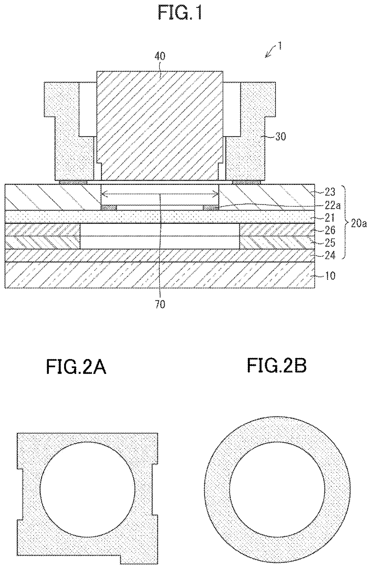
[0017]An outline of a display apparatus 1 according to Embodiment 1 of the disclosure will be described with reference to FIG. 1. FIG. 1 is a schematic view of the display apparatus 1.

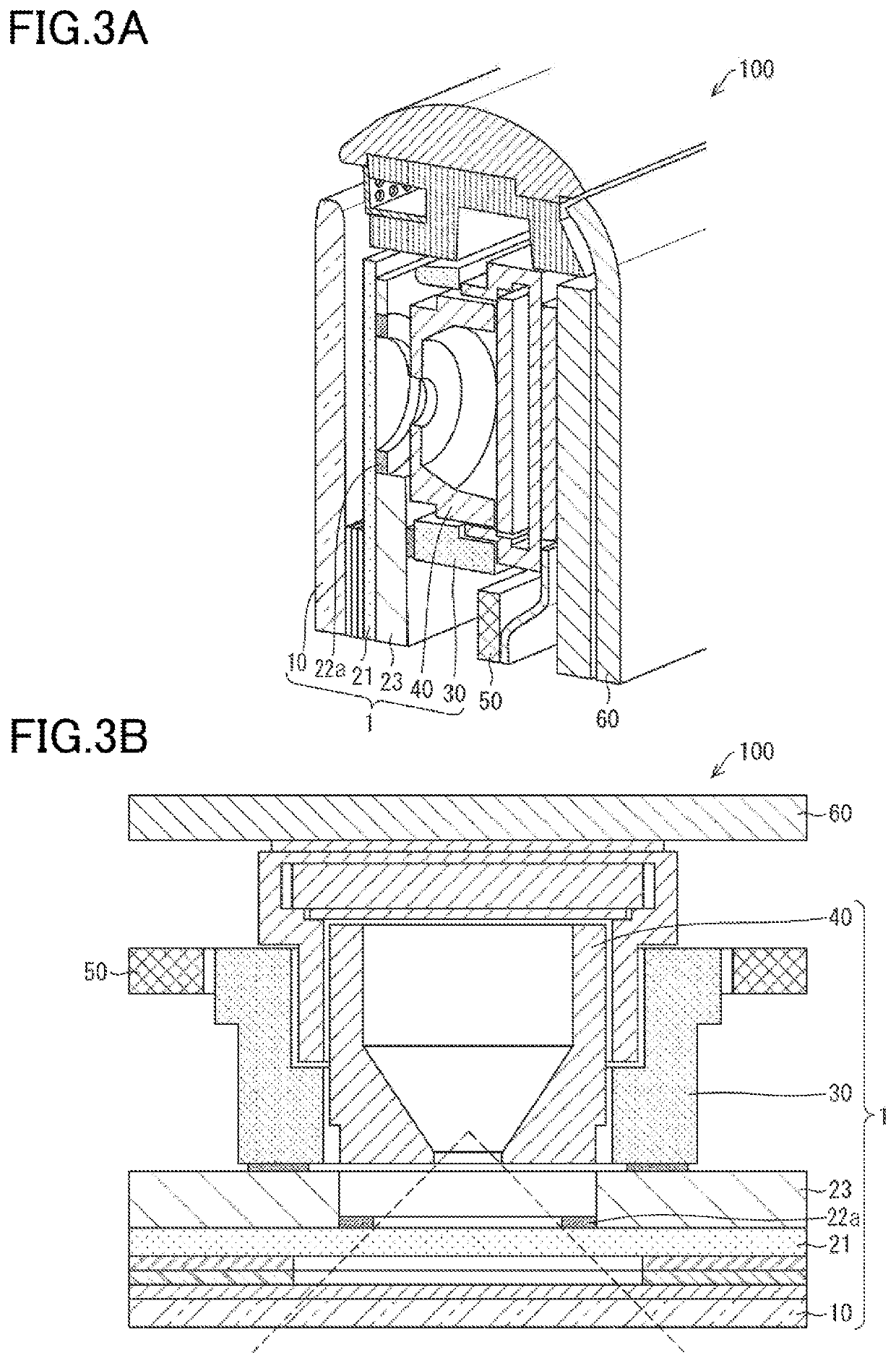
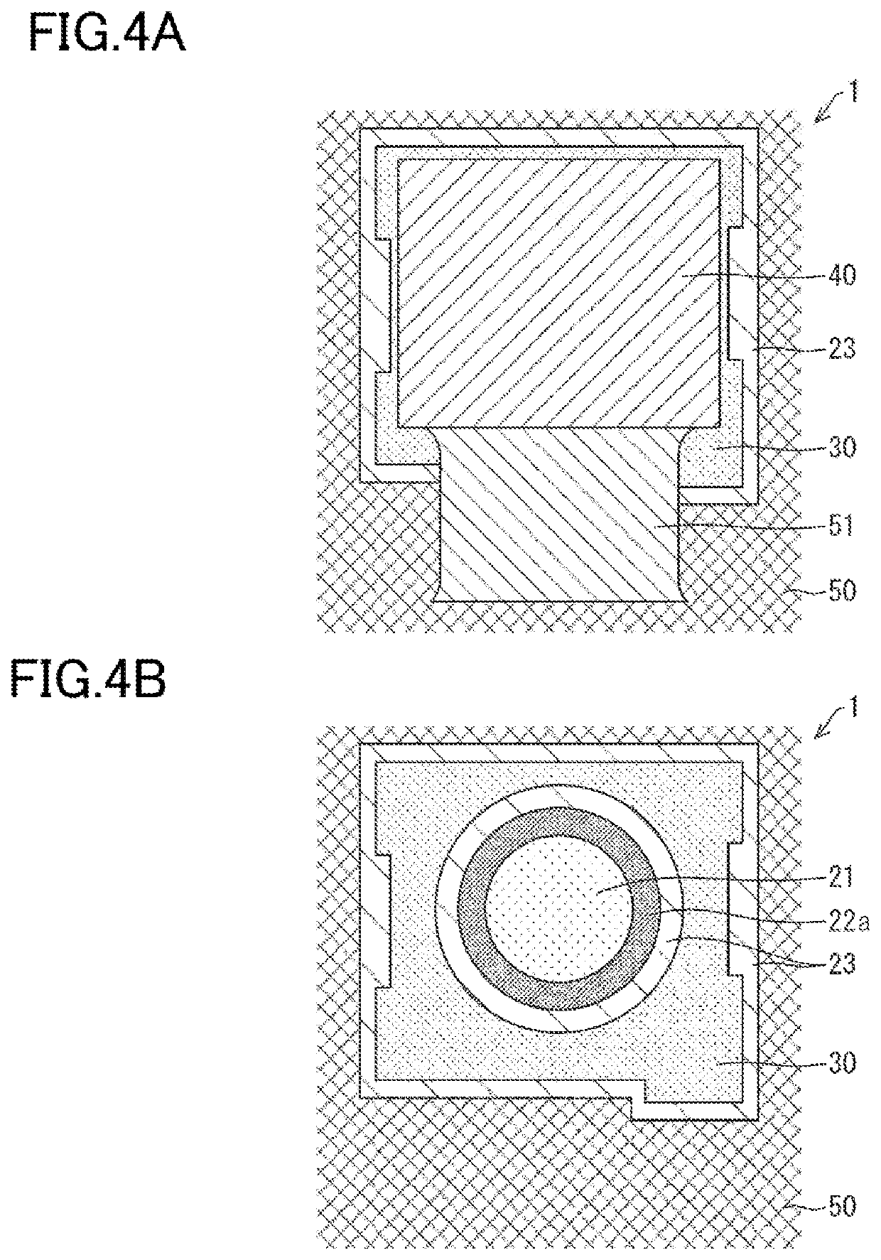
[0018]The display apparatus 1 includes a screen 10, a display element 20a, a fixing member: 30, and a device 40.

[0019]The screen 10 is formed of a material, such as glass or resin, through which light is transmitted, and forms an outermost surface of the display apparatus 1.

[0020]The display element 20a is a liquid crystal display element and is provided so as to contact the screen 10 in an opposed manner. A liquid crystal display element is used as the display element 20a in the display apparatus 1 according to Embodiment 1.

[0021]The display element 20a includes at least a liquid crystal panel 21 and a backlight 23. In addition to the liquid crystal panel 21 and the ba...

embodiment 2

[0033]Another embodiment of the disclosure will be described below. Note that, for convenience of description, members having the same functions as those of the members described in the embodiment described above will be given the same reference signs and description thereof will not be repeated.

[0034]A display apparatus 2 according to Embodiment 2 of the disclosure is illustrated in FIG. 5. The display-apparatus 2 according to the present embodiment is different from the display apparatus 1 of Embodiment 1 described above in that an organic EL display element is used as a display element 20b. Thus, as illustrated in FIG. 5, the display apparatus 2 according to the present embodiment includes, as the display element 20b, the OCA tape 25, a transparent display device 27, and the opening 70, and has a device 41 fixed to a print 22b. Note that, the print 22b is formed on the transparent display device 27. A configuration other than the configuration described above is similar to that o...

embodiment 3

[0035]Another embodiment of the disclosure will be described below. Note that, for convenience of description, members having the same functions as those of the members described in the embodiments described above will be given the same reference signs and description thereof will not be repeated.

[0036]A display apparatus 3 according to Embodiment 3 of the disclosure is illustrated in FIG. 6. The display-apparatus 3 according to the present embodiment is different from the display apparatus 1 of Embodiment 1 described above in that an organic light emitting diode display element is used as a display element 20c. Thus, as illustrated in FIG. 6, the display apparatus 3 according to the present embodiment includes, as the display element 20c, the touch panel 24, the OCA tape 25, an organic light emitting diode panel 28, and a protection sheet 29, and has a device 42 fixed to the OCA tape 25. Note that, a print 22c is formed on the OCA tape 25. A configuration other than the configurati...


PUM


Abstract

A display apparatus includes a display element which faces a screen and in which an opening that allows transmission of light from outside, which has passed through the screen, is formed. A device that inputs and outputs information to electronic equipment is fixed to the display element through a fixing member, which is installed on the display element, so that the device is able to receive the light transmitted through the opening.

Description

BACKGROUND1. Field[0001]The present disclosure relates to a display apparatus and electronic equipment.2. Description of the Related Art[0002]A mobile phone or the like has a device, such as a camera module, installed between a display screen and a housing, for example, in order for a user to make a call while seeing a face of a called party. Thus, in the display screen, an opening through which light is transmitted is formed at a position where the device is provided.[0003]Japanese Unexamined Patent Application Publication No. 2012-70356 (published on Apr. 5, 2012) discloses a method of installing a sensor on a back side of a display screen such as an organic Electro Luminescence (EL) display to visually obscure the sensor when viewed from a front side of the display screen.[0004]In the related art as described above, however, when a display screen and a substrate or the like are installed, a positional shift is caused between the opening formed in the display screen and the device...

Claims


Application Information

Patent Timeline
IPC IPC(8): H04N5/225H05K5/00
CPCH01L27/32H04N5/2257H04N5/2253G02F1/1336H05K5/0017H04M1/0266H04M1/0264G02F1/1333G02F1/133308G02F1/13318G09G3/3406G09G2300/0404G03B2217/002G06F1/1686G06F1/1637G02B5/005H04N23/57H04N23/54H10K59/00
Inventor TAKAHASHI, JUNYA
Owner SHARP KK
Why Eureka
Try Eureka