Method of manufacturing display panel

Inactive Publication Date: 2008-12-04
DENSO CORP
View PDF2 Cites 8 Cited by
  • Summary
  • Abstract
  • Description
  • Claims
  • Application Information

AI Technical Summary

Benefits of technology

[0013]The present invention is made in view of the foregoing matter, and it is an object of the present invention to provide a method of manufacturing a display panel, capable of reducing projections and depressions of a surface of a printed layer and enhancing a design.
[0015]Accordingly, the display panel including the base and the printed layer is produced. When the color UV curable ink is deposited on the base by inkjet printing, projections and depressions are generated between a region where the color printed portion is formed and a region where the color printed portion is not formed on the base, and / or between a region where the thickness of the color printed portion is large and a region where the thickness of the color printed portion is small. That is, the first depression corresponds to the region where the color printed portion is not formed on the base, and the second depression corresponds to the portion where the thickness of the color printed portion is smaller than the other portion, such as creases provided between rounded ridges of the color printed portion that is formed in a regular linear pattern. Since the transparent UV curable ink is deposited in at least one of the first depression and the second depression, the projections and depressions of a surface of the printed layer are reduced. That is, the printed layer has a generally smooth surface. Therefore, an appearance of the display panel enhances. Thus, the display panel provides an enhanced design.

Problems solved by technology

Also, because accuracy of printing positions and resolution are generally low, a printing design is likely to be restricted.
Because an inkjet printing device generally has a simple mechanism, an initial cost is generally low.
Also, if the solvent-type ink is deposited to the surface of such base plates by inkjet printing, ink droplets are likely to be condensed before being dried, and the base plates are likely to be melted and deformed.
In this case, it is difficult to maintain the predetermined image.
As a result, the surface of the printed layer have rounded ridges and an appearance of the display panel will be deteriorated due to unevenness, such as projections and depressions, of the surface of the printed layer.
Further, since the UV curable ink is cured immediately after being deposited on the panel, the projections and depressions are likely to be more visible.

Method used


Image

  • Method of manufacturing display panel
  • Method of manufacturing display panel
  • Method of manufacturing display panel

Examples


first embodiment

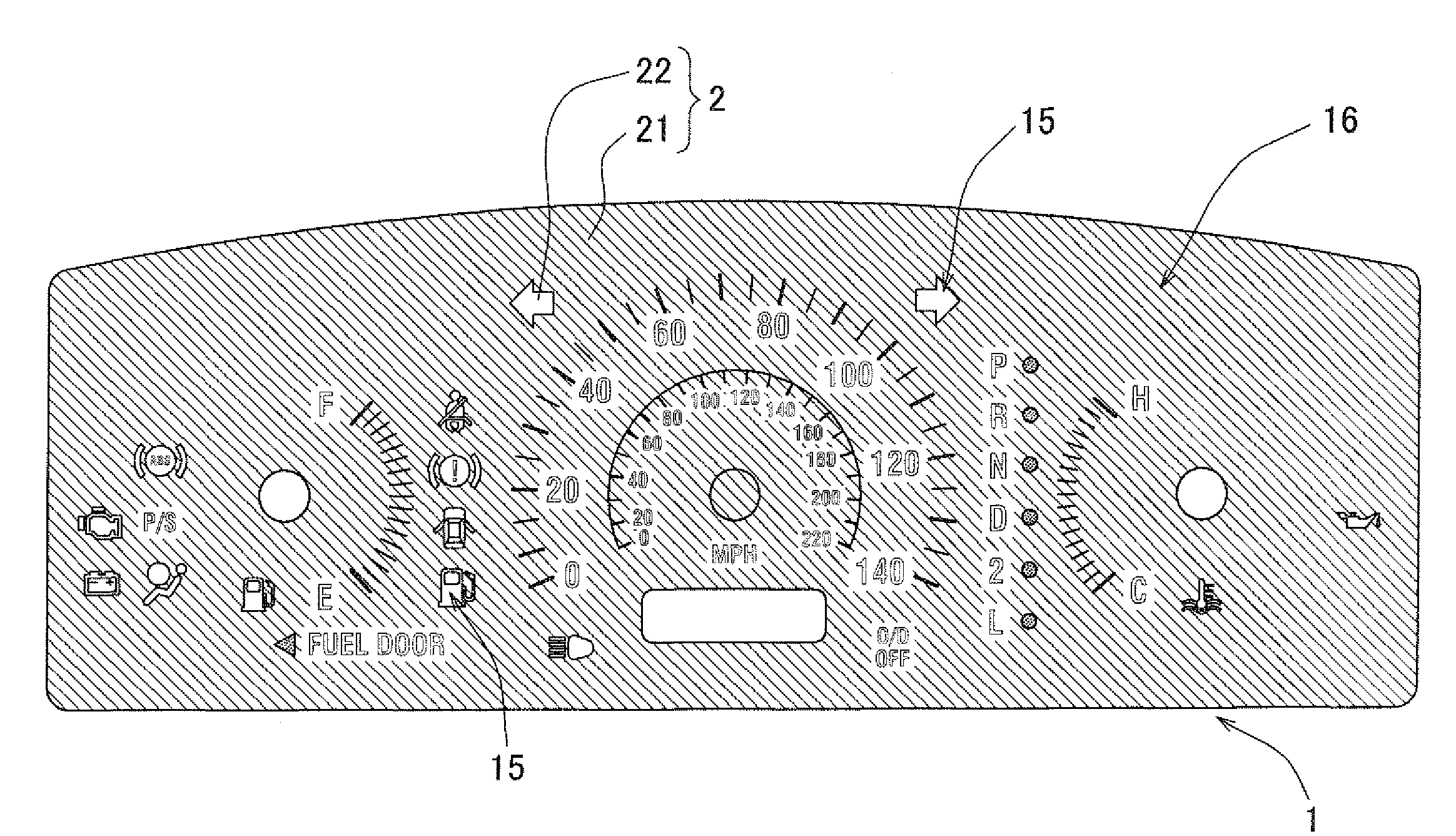
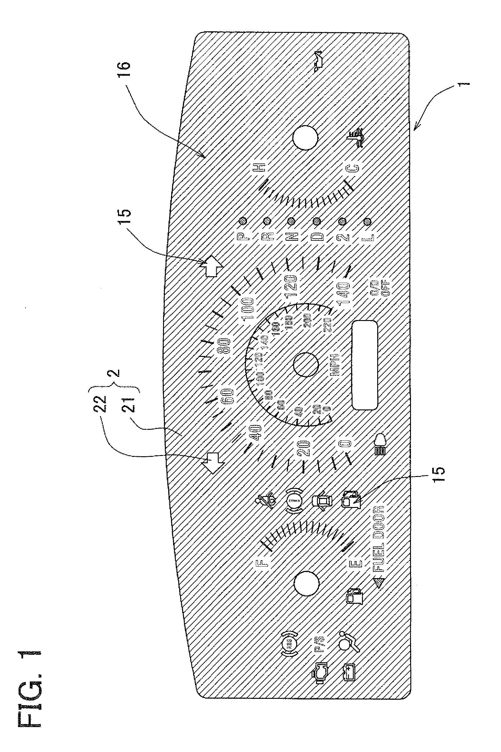
[0049]Referring to FIGS. 1 to 3, a display panel 1 of the present embodiment is exemplarily employed as a meter panel, that is, a dial board of a vehicular instrument.

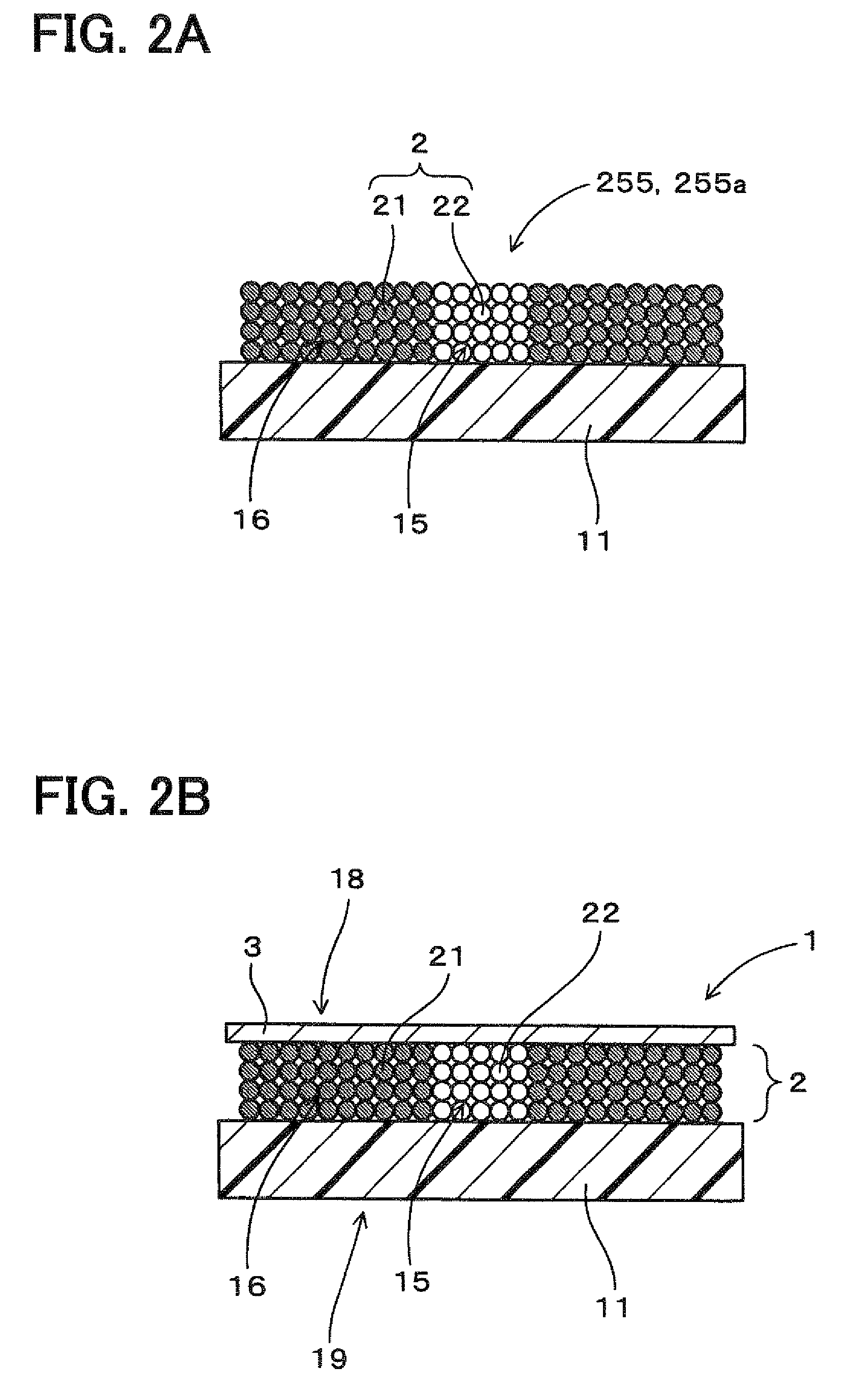
[0050]As shown in FIGS. 1 and 2B, the display panel 1 has a resinous base plate (resinous base) 11 and a printed layer 2 printed on a surface of the resinous base plate 11 by inkjet printing using UV curable ink. In the inkjet printing, the UV curable ink is deposited on the surface of the resinous base plate 11 and cured thereon.

[0051]The printed layer 2 includes a color printed portion (e.g., color printed layer) 21 and a transparent printed portion (e.g., transparent printed layer) 22. FIG. 2B shows a boundary of the color printed portion 21 and the transparent printed portion 22.

[0052]The resinous base plate 11 is, for example, made of a resin material having transparency, such as polycarbonate. The display panel 1 includes a transparent portion 15 that allows light to pass through and an opaque portion 16 that doe...

second embodiment

[0072]In the second embodiment, the overcoat layer 3 for matting is formed in a nonlinear pattern by depositing a transparent UV curable ink in a discontinuous manner.

[0073]First, as shown in FIG. 9, the printed layer 2 including the color printed portion 21 and the transparent printed portion 22 is formed on the base plate 11 by inkjet printing using the UV curable ink. Similar to the first embodiment, the transparent printed portion 22 is formed such that the height difference between the transparent printed portion 22 and the color printed portion 21 is equal to or less than 30 μm.

[0074]Then, the overcoat layer 3 is formed by depositing and curing the transparent UV curable ink over the printed layer 2 by inkjet printing. FIGS. 7 and 8 show a printing pattern of the overcoat layer 3.

[0075]That is, the transparent UV curable ink is deposited over the printed layer 2 in patterns in which ink particles 30 do not contact each other or less contact each other, as shown in FIGS. 9A and...


PUM

PropertyMeasurementUnit
Heightaaaaaaaaaa
Transparencyaaaaaaaaaa

Abstract

In a method of manufacturing a display panel that includes a base and a printed layer printed on the base by inkjet printing, a color UV curable ink is deposited on a predetermined portion of the base for forming a color printed portion of the printed layer, and a transparent UV curable ink is deposited in at least one of a first depression provided by the color printed portion on a surface of the base and a second depression formed on a surface of the color printed portion for forming a transparent printed portion.

Description

CROSS REFERENCE TO RELATED APPLICATION[0001]This application is based on Japanese Patent Application No. 2007-141565 filed on May 29, 2007, the disclosure of which is incorporated herein by reference.FIELD OF THE INVENTION[0002]The present invention relates to a method of manufacturing a display panel for a display device such as an instrument for a vehicle.BACKGROUND OF THE INVENTION[0003]In a vehicle, for example, a display device such as an instrument is installed in front of a driver's seat. The display device is generally constructed of a display panel, a light source arranged on a rear side of the display panel, and the like. The display panel has design portions including a scale, characters, indicators and the like. The design portions are provided by a printed layer formed on a base plate of the display panel. Such a display device is, for example, described in Japanese Unexamined Patent Application Publications No. 2004-286459 (U.S. Pat. No. 6,856,478), No. 2005-321343, No...

Claims


Application Information

Patent Timeline
IPC IPC(8): B05D1/36
CPCB41M5/0047B41M5/0064B60K37/02B60Y2410/12G01D13/12B41M7/0081B41M7/0027B60K35/60
Inventor IWASE, TERUHIKOKOURA, TOSHIO
Owner DENSO CORP
Why Eureka
Try Eureka