
Buckle belt assembly

a buckle belt and assembly technology, applied in the field can solve the problems of buckle belt being skewed relative to the outer casing, flexible cable deformation, unstable hanging objects, etc., and achieve the effect of simple operation, improved load-carrying capability of buckle belt assembly, and easy opening and closing

Active Publication Date: 2020-02-20
TSAI HAI PIN
View PDF9 Cites 4 Cited by
  • Summary
  • Abstract
  • Description
  • Claims
  • Application Information

AI Technical Summary

Benefits of technology

The present disclosure describes a buckle belt assembly that is easy to operate and has improved load-carrying capacity. It can be opened and closed with a simple press of the side walls, and the hanging objects attached to it do not detach when not in use. This design ensures accurate positioning of the buckle belt assembly when the cable is restored. The buckle belt assembly includes a main body and a sleeved buckle belt with a supporting portion, movable portion, and a band for hanging objects. The band is a flexible and bendable plastic element, and it can be opened or closed by pressing the side walls. This buckle belt assembly provides a simple yet effective solution for carrying and retaining hanging objects.

Problems solved by technology

(1) The buckle belt of the buckle belt assembly is directly pulled, which is not an ideal design. As the number of uses increases, the buckle belt may be worn, causing the hanging objects to be unstable and easily to be lost.
(2) The conventional buckle belt assembly has a limited load-carrying capability. The restoring device and the flexible cable may be deformed and failed when the load is too great. When the buckle belt is automatically restored by the restoring device, the buckle belt and the outer casing are not able to be accurately positioned and accommodated, which may cause the buckle belt to be skewed relative to the outer casing, and may affect the use and aesthetics of the buckle belt assembly.

Method used


Image

  • Buckle belt assembly
  • Buckle belt assembly
  • Buckle belt assembly

Examples


Embodiment Construction

[0025]In order to explain the technical solution of the present disclosure more clearly and completely, the present disclosure will be further described in accompanying with the drawings.

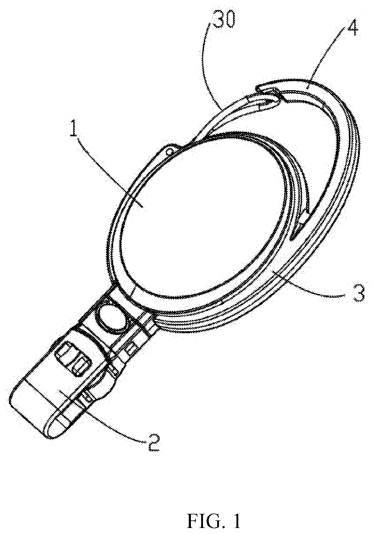
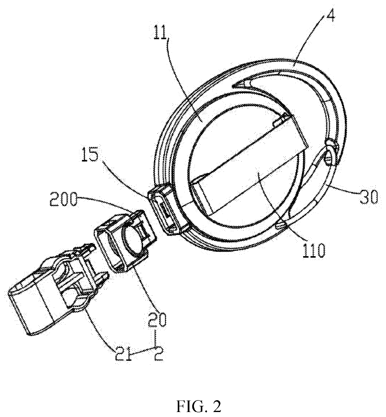
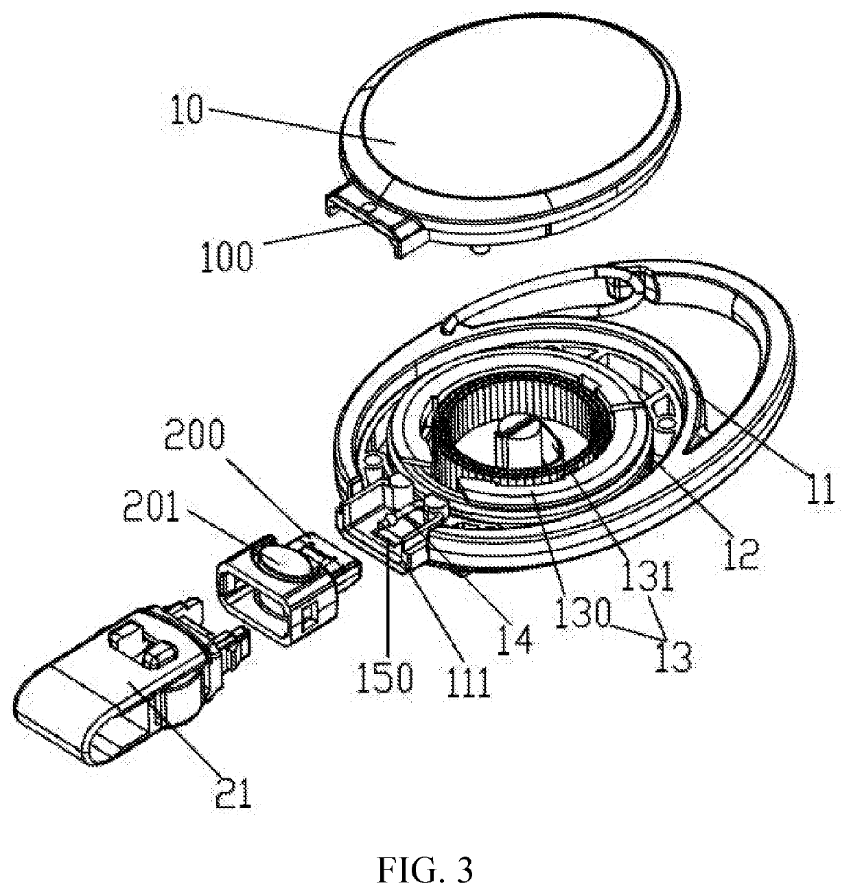
[0026]Referring to FIGS. 1-7, the present disclosure relates to a buckle belt assembly. The buckle belt assembly includes a main body 1 and a buckle belt 2. The main body 1 includes an upper shell 10, a lower shell 11, an accommodating cavity 12 being formed by fastening the upper shell 10 with the lower shell 11, a restoring device 13 being configured within the accommodating cavity 12, a cable 14 being winded on the restoring device 13 and having one end being fixed to the restoring device 13, and a receiving groove 15 communicating with the accommodating cavity 12. The receiving groove 15 is formed by simultaneously extending the upper shell 10 and the lower shell 11 outwardly. The other end of the cable 14 is fixed to the buckle belt 2. The buckle belt 2 includes an insertion end 200 and a first...


PUM


Abstract

The present disclosure relates to a buckle belt assembly, including: a main body and a buckle belt. The buckle belt includes a first body and a second body sleeved on the first body. The second body includes a supporting portion, a second movable portion, and a band extending from a bottom of the supporting portion. One end of the second movable portion is connected to the supporting portion, and the other end of the second movable portion is movable relative to the supporting portion. The second movable portion includes a pair of side walls and a pair of fixing walls. The band is configured to hang hanging objects, the band is configured with a fixing hole, and the side walls are pressed to abut the fixing wall to the fixing hole or to detach the fixing wall from the fixing hole, thereby opening or closing the band.

Description

FIELD OF THE INVENTION[0001]The present disclosure relates to pendant and accessory field, and more particularly to a buckle belt assembly configured to fasten a key, a mobile phone, or a certification card.BACKGROUND OF THE INVENTION[0002]The conventional buckle belt assembly may include an outer casing, a restoring device configured within an inner cavity of the outer casing, a flexible cable, and a buckle belt. The conventional buckle belt assembly is configured to hang the portable objects, such as keyrings, working cards, and access cards. The buckle belt may be pulled away from the outer casing when the portable objects are in use, and may automatically be restored by the restoring device when the portable objects are not in use. The conventional buckle belt assembly is convenient for storage and is popular among enterprise employees and home users. However, the conventional buckle belt assembly may have the following problems.[0003](1) The buckle belt of the buckle belt assem...

Claims


Application Information

Patent Timeline
Patent Type & Authority Applications(United States)
IPC IPC(8): A45F5/02A44B11/26
CPCA44B11/266A44B11/006A45F5/021A44B11/22A44B11/2592A44B15/005
Inventor TSAI, HAI PIN
Owner TSAI HAI PIN
Learn More