
Portable medical vacuum suction device

a vacuum suction device and portable technology, applied in the direction of suction drainage containers, intravenous devices, other medical devices, etc., can solve the problems of not having the means to arbitrarily control the amount of body fluid discharged by means of a user, noise and vibration, and battery needs to be also needed, so as to achieve convenient use

Inactive Publication Date: 2020-02-20
LEE HYUN WOO
View PDF0 Cites 3 Cited by
  • Summary
  • Abstract
  • Description
  • Claims
  • Application Information

AI Technical Summary

Benefits of technology

The present invention is a medical vacuum suction device that can be used to forcibly discharge body fluids using a vacuum pressure. The device is portable and easy to use. It has a flow rate control member that allows the user to control the amount of body fluid discharged. It also has a corrugated tube that allows the user to check the vacuum state with the naked eyes. These features make the device convenient and efficient for medical purposes.

Problems solved by technology

However, there is no means for arbitrarily controlling an amount of body fluid discharged by means of a user.
Due to the use of the vacuum motor, however, noise and vibrations are generated during the use, and the battery has to be also needed.

Method used


Image

  • Portable medical vacuum suction device
  • Portable medical vacuum suction device
  • Portable medical vacuum suction device

Examples


Embodiment Construction

[0023]Hereinafter, the present invention will now be described in detail with reference to the attached drawings. Before the present invention is disclosed and described, it is to be understood that the disclosed embodiments are merely exemplary of the invention, which can be embodied in various forms. If it is determined that the detailed explanation on the well known technology related to the present invention makes the scope of the present invention not clear, the explanation will be avoided for the brevity of the description. Even though the corresponding parts in the embodiments of the present invention have somewhat different structures, the parts having the same functions as each other are indicated by corresponding reference numerals.

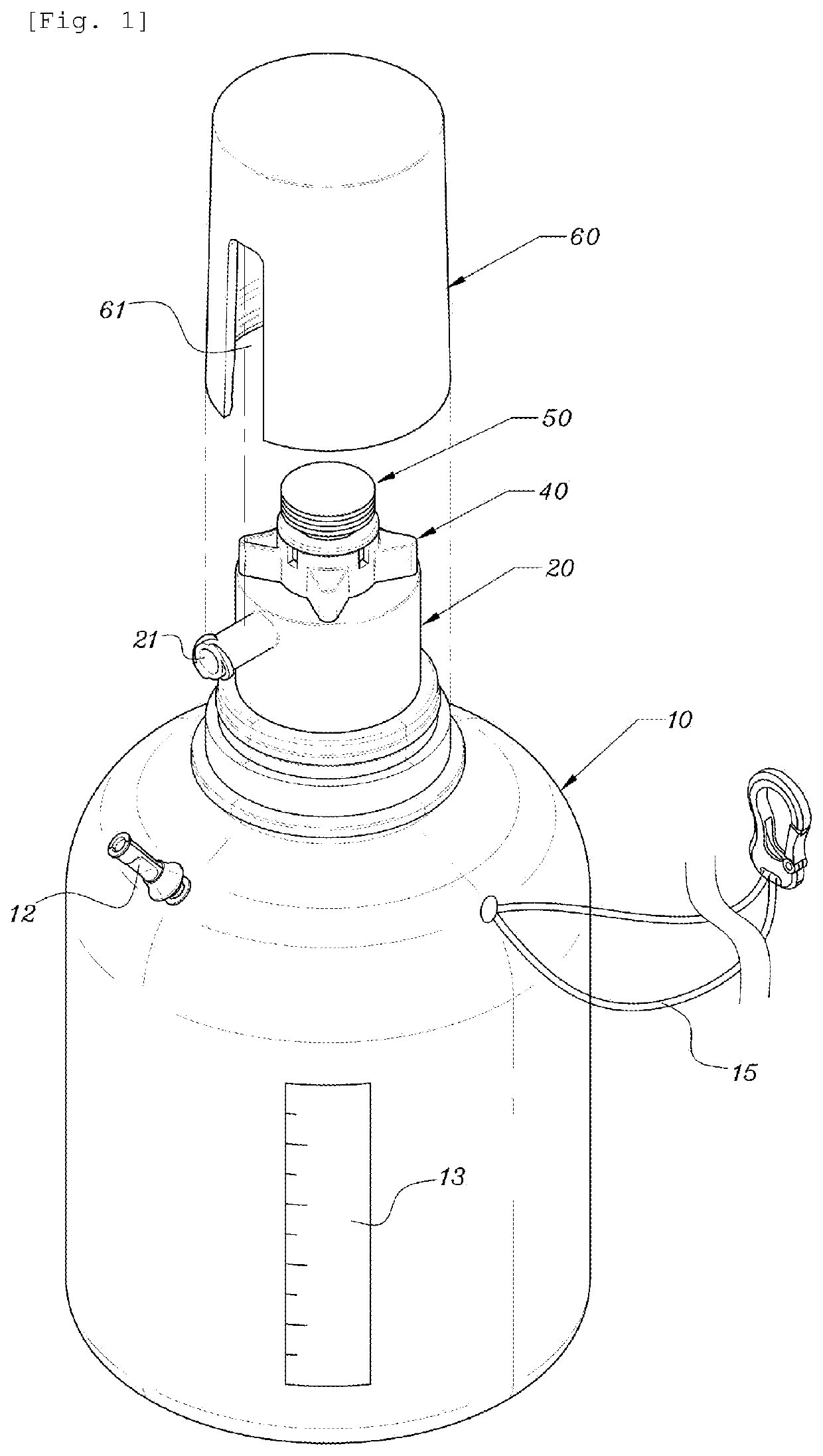
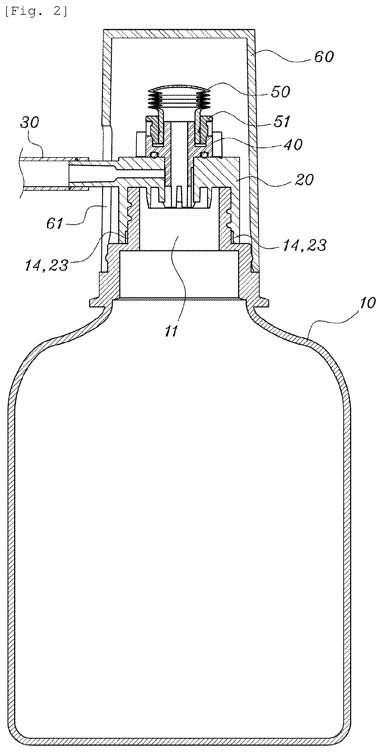
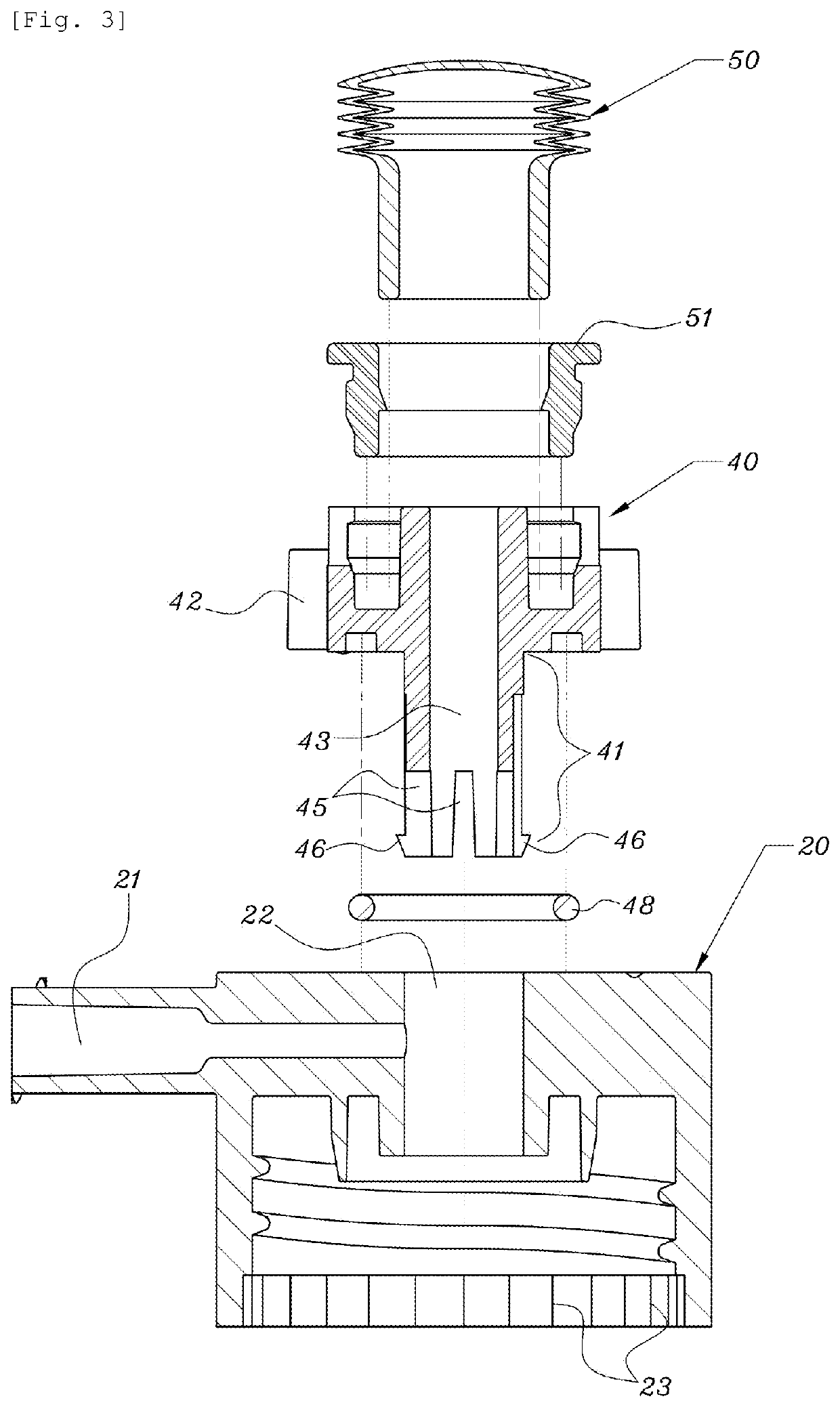
[0024]As shown in FIGS. 1 and 2, a portable medical vacuum suction device according to the present invention includes a suction container 10 provided with an internal space in a vacuum state, a connection cap 20 coupled to an inlet of the suctio...


PUM


Abstract

The present invention relates to a medical vacuum suction device used for forcibly discharging various body fluids and, more particularly, to a portable vacuum suction device comprising: a suction container provided with an internal space in a vacuum state; a connection cap coupled to an inlet of the suction container; a drain tube for guiding the discharge of a body fluid toward the connection cap; a flow rate control member for controlling the flow rate of the body fluid; and a soft corrugated tube which contracts or expands according to the vacuum pressure of the suction container.

Description

TECHNICAL FIELD[0001]The present invention relates to a medical vacuum suction device used for forcibly discharging various body fluids and, more particularly, to a portable vacuum suction device including: a suction container provided with an internal space in a vacuum state; a connection cap coupled to an inlet of the suction container; a drain tube for guiding the discharge of a body fluid toward the connection cap; a flow rate control member for controlling the flow rate of the body fluid; and a soft corrugated tube which contracts or expands according to the vacuum pressure of the suction container.BACKGROUND ART[0002]Generally, a medical suction device is a medical instrument for forcibly discharging a body fluid secreted from an operating portion of a patient or an airway of a patient in the intensive care unit, and the device includes a negative pressure providing means for providing a suction force, a storage container for storing the body fluid discharged by means of the s...

Claims


Application Information

Patent Timeline
Patent Type & Authority Applications(United States)
IPC IPC(8): A61M1/00
CPCA61M1/0088A61M1/0027A61M1/0082A61M1/0031A61M1/0003A61M1/732A61M1/743A61M1/66A61M39/24A61M2205/3334A61M2202/0014A61M1/84A61M1/74
Inventor LEE, HYUN WOO
Owner LEE HYUN WOO
Learn More