
Contact vibration detection device, rotary machine including the same, and contact vibration detection method

a technology of contact vibration and detection device, which is applied in the direction of vibration measurement in solids, instruments, and static/dynamic balance measurement, etc., can solve the problems of rotational shaft bending, contact vibration, and the degree of unbalance may chang

Active Publication Date: 2020-02-20
MITSUBISHI HEAVY IND LTD
View PDF0 Cites 0 Cited by
  • Summary
  • Abstract
  • Description
  • Claims
  • Application Information

AI Technical Summary

Benefits of technology

The present invention provides a device, a machine, and a method to detect the vibration of rotary machines when they make contact.

Problems solved by technology

During rotation of the rotational shaft, the rotational shaft may come into contact with a stationary part such as a seal part and an oil thrower part, which causes contact vibration.
Further, contact between the rotational shaft and the stationary part increases the temperature of the contact portion and causes the rotational shaft to bend.
When the rotational shaft bends, the degree of unbalance may change.

Method used


Image

  • Contact vibration detection device, rotary machine including the same, and contact vibration detection method
  • Contact vibration detection device, rotary machine including the same, and contact vibration detection method
  • Contact vibration detection device, rotary machine including the same, and contact vibration detection method

Examples


Embodiment Construction

[0039]Embodiments of the present invention will now be described in detail with reference to the accompanying drawings. However, the following embodiments and the drawings are illustrative only, and various modifications may be applied as long as they do not depart from the object of the present invention. Further, two or more embodiments may be optionally combined in any manner. Further, in the following embodiments, similar elements will be indicated by the same reference numerals, and redundant descriptions thereof will be omitted for convenience.

[0040]It is intended, however, that unless particularly specified, dimensions, materials, shapes, relative positions and the like of components described in the embodiments shall be interpreted as illustrative only and not intended to limit the scope of the present invention.

[0041]For instance, an expression of relative or absolute arrangement such as “in a direction”, “along a direction”, “parallel”, “orthogonal”, “centered”, “concentri...


PUM


Abstract

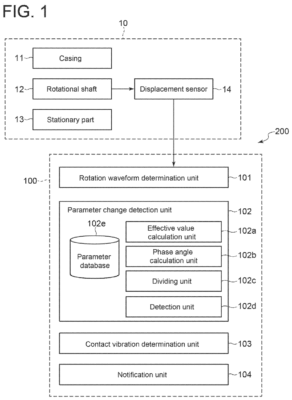
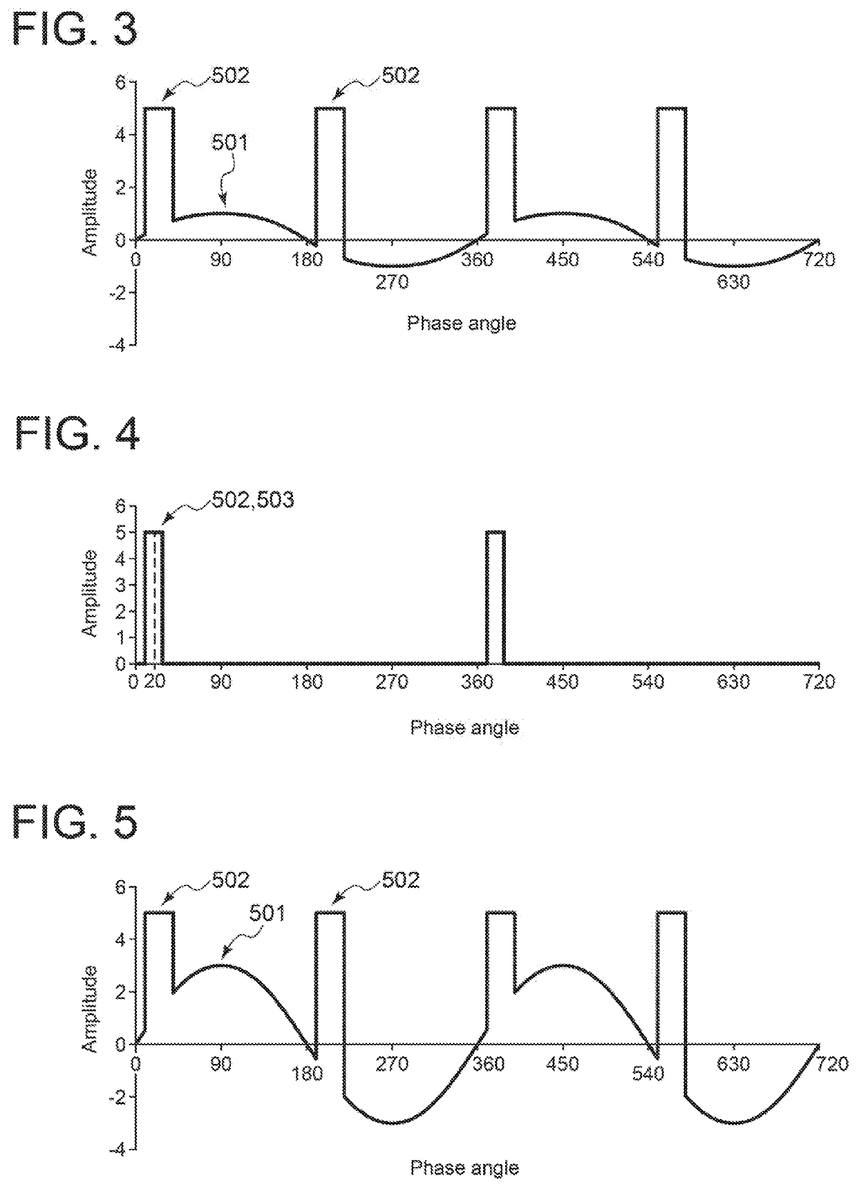
A contact vibration detection device 100 for detecting contact vibration due to contact between a rotational shaft 12 and a stationary part 13 includes: a rotation waveform determination unit 101 configured to determine a rotation waveform of the rotational shaft 12 based on displacement of the rotational shaft 12 during rotation; a parameter change detection unit 102 configured to detect a change in a parameter of at least one of an effective value of the rotation waveform or a phase angle of the rotation waveform; and a contact vibration determination unit 103 configured to determine whether the contact vibration occurs based on presence or absence of the change in the parameter.

Description

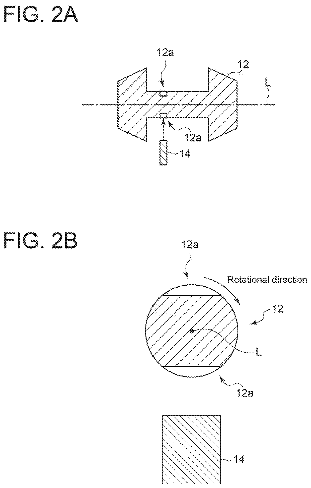
TECHNICAL FIELD[0001]The present invention relates to a contact vibration detection device, a rotary machine including the same, and a contact vibration detection method.BACKGROUND ART[0002]In a rotary machine such as a turbo machine, a turbine, and a compressor, a rotational shaft rotates. During rotation of the rotational shaft, the rotational shaft may come into contact with a stationary part such as a seal part and an oil thrower part, which causes contact vibration. Further, contact between the rotational shaft and the stationary part increases the temperature of the contact portion and causes the rotational shaft to bend. When the rotational shaft bends, the degree of unbalance may change. In this case, contact vibration is further amplified.[0003]As described above, once contact vibration occurs, contact vibration may gradually increase. Therefore, it is preferable to stop rotation of the rotary machine when contact vibration is detected, in view of appropriate maintenance of...

Claims


Application Information

Patent Timeline
Patent Type & Authority Applications(United States)
IPC IPC(8): G01M1/22
CPCG01M1/22G01M13/00G01H9/00G01H3/00G01H1/003G01M13/028
Inventor YOSHIDA, TADASHISASAKI, RYOJINISHIMURA, HIDETAKATSUJI, TAKESHI
Owner MITSUBISHI HEAVY IND LTD
Learn More