
Flywheel-driven setting tool and method for operating such a setting tool

a technology of setting tool and setting tool, which is applied in the direction of manufacturing tools, nailing tools, etc., can solve the problems of coupling clamping rate, coupling device jamming, and increased plunger mispositioning ra

Inactive Publication Date: 2020-02-27
HILTI AG
View PDF0 Cites 1 Cited by
  • Summary
  • Abstract
  • Description
  • Claims
  • Application Information

AI Technical Summary

Benefits of technology

The patent describes a flywheel-driven setting device that is used to drive a fastening element into a substrate. The device includes an electric motor that rotates a flywheel, which is connected to a driving element through a coupling device. The coupling device is designed to open after the setting process is complete, allowing the driving element to return to its starting position. This eliminates the need for the user to manually adjust the driving element. The device also includes a detection device that can detect mispositioning of the driving element, and an actuator that can open the coupling device after a set amount of time has passed or when the device is pressed against the substrate. The technical effects of this invention include improved operational efficiency, reduced user effort, and automatic correction of mispositioning.

Problems solved by technology

An undesired mispositioning of the driving element can lead to jamming of the coupling device, in particular in the case of coupling devices with self-reinforcement.
In wood applications, due to natural material inhomogeneities, for example in the form of knotholes, an increased plunger mispositioning rate or coupling clamping rate occurs, which is undesirable.

Method used


Image

  • Flywheel-driven setting tool and method for operating such a setting tool
  • Flywheel-driven setting tool and method for operating such a setting tool
  • Flywheel-driven setting tool and method for operating such a setting tool

Examples


Embodiment Construction

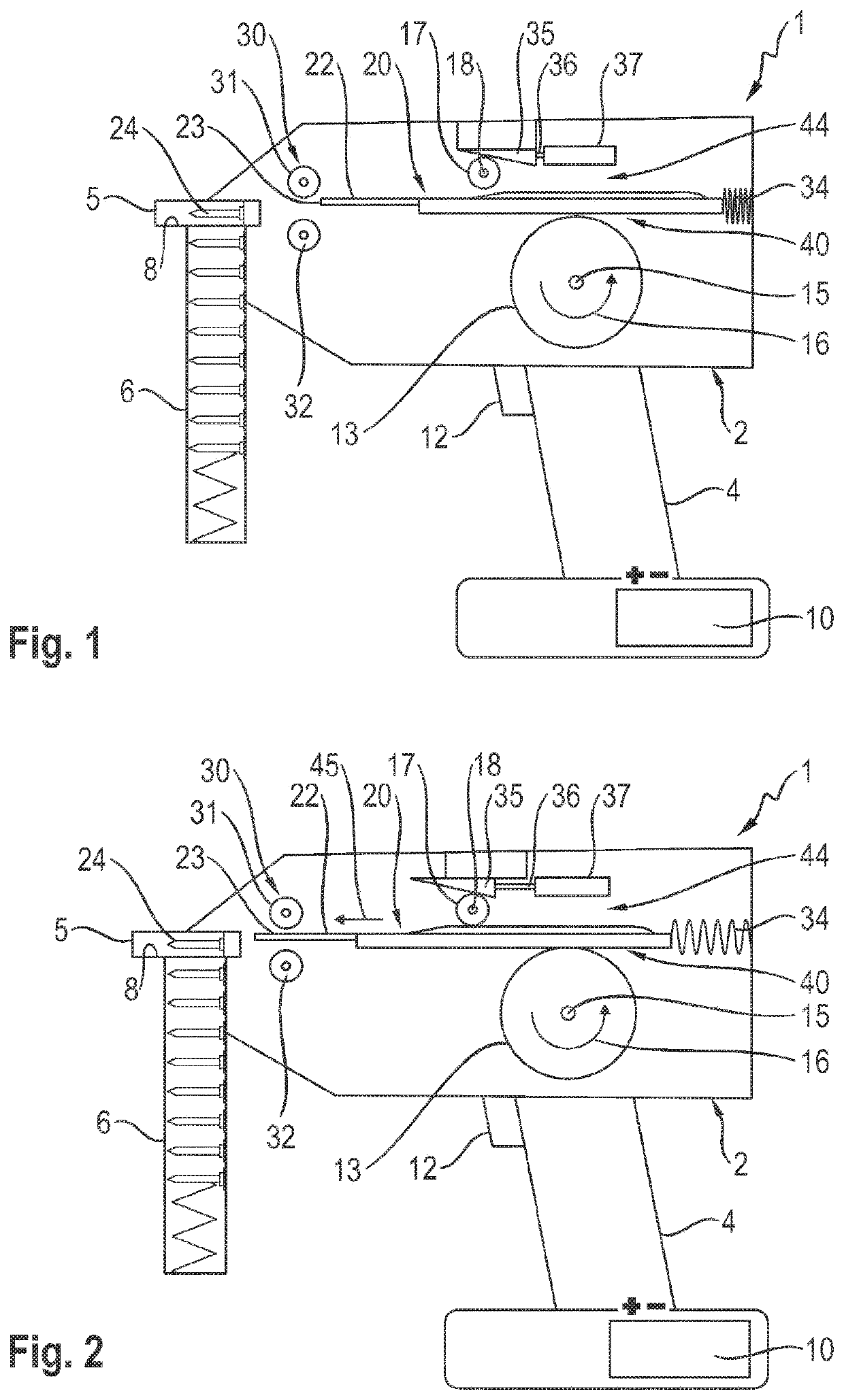
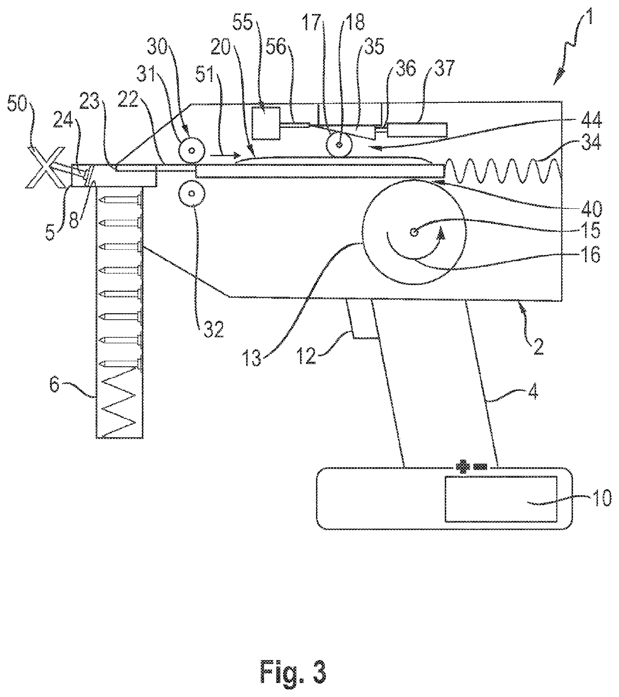
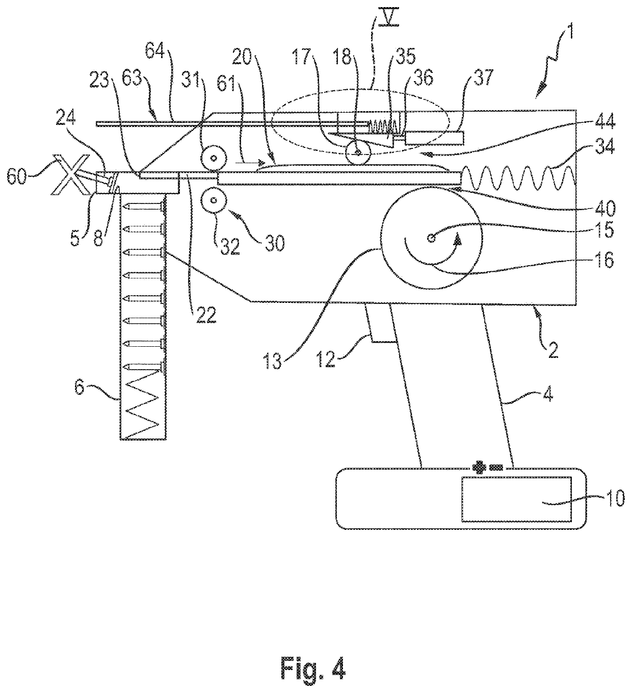
[0024]In FIGS. 1 and 2, a flywheel-driven setting device 1 having a housing 2 is shown in a simplified manner. The setting device 1 is designed as a hand-operated setting device with a handle 4 and a setting end 5.

[0025]The setting device or setting tool 1 is used for driving fastening elements 24 into a substrate (not shown). A desired number of fastening elements 24 is stored in a magazine 6 at the setting end 5. The fastening elements 24 are individually provided from the magazine 6, preferably automatically, into a bolt guide 8.

[0026]The energy required for driving in the fastening elements 24 is provided, for example, in the form of electrical energy in an accumulator 10 at the lower end of the handle 4. The electrical energy stored in the accumulator 10 is converted into rotational energy by means of an electric motor (not shown), which is advantageously integrated in a flywheel 13.

[0027]By means of this rotational energy, the flywheel 13 is rotated about a flywheel rotation a...


PUM


Abstract

A flywheel-driven setting tool comprising a flywheel which can be drivingly connected to a drive-in element by a coupling device in order to drive a securing element into an underlying surface during a setting process using the drive-in element, wherein the drive-in element is accelerated out of a starting position in a setting direction. In order to allow securing elements to be driven into the underlying surface in a consistent manner, the coupling device is paired with an actuator, by which the coupling device can be opened.

Description

TECHNICAL FIELD[0001]The invention relates to a flywheel-driven setting device comprising a flywheel which can be drivingly connected to a driving element by means of a coupling device in order to drive a fastening element into a substrate during a setting process using the driving element, wherein the driving element is accelerated out of a starting position in a setting direction. The invention also relates to a method for operating such a setting device.PRIOR ART[0002]The European publications EP 2 716 409 A2, EP 2 711 135 A2 and EP 2 433 752 A2 disclose various setting tools, which produce a frictional connection between a plunger and a flywheel during a setting process, in order to transmit rotational energy from the flywheel to the plunger.SUMMARY OF THE INVENTION[0003]The object of the invention is to simply enable a uniform driving of fastening elements into a substrate by means of a flywheel-driven setting device according to the preamble of claim1, in particular with the l...

Claims


Application Information

Patent Timeline
Patent Type & Authority Applications(United States)
IPC IPC(8): B25C1/06B25C1/00
CPCB25C1/06B25C1/008
Inventor DITTRICH, TILOSCHMIDT, DOMINIKTHON, RAPHAEL
Owner HILTI AG
Learn More