
System and method for robotic gripping utilizing dynamic collision modeling for vacuum suction and finger control

a dynamic collision modeling and robotic technology, applied in the field of robotic gripping systems, can solve the problems of limited ability of current robotic system, limited size, weight, and size of objects that existing robotic grippers that incorporate vacuum suction can manipula

Active Publication Date: 2020-03-12
OCADO INNOVATION
View PDF0 Cites 9 Cited by
  • Summary
  • Abstract
  • Description
  • Claims
  • Application Information

AI Technical Summary

Benefits of technology

The patent describes a robotic apparatus for manipulating objects using a vacuum port and gripping structures. The apparatus uses a dynamic collision model for motion planning and a contact sensor to determine the object's position. The controller can selectively and individually actuate the vacuum port and gripping structures, and can modify the motion path if there is a possibility of collision. The technical effects of this invention include improved object manipulation and safety during robotic manipulation.

Problems solved by technology

Common robotic end effectors with gripping functionality are frequently highly complex, and highly customized to match the handled work piece.
However, current systems have in in handling irregularly-shaped objects, and current robotic system are limited in their ability to be widely used for different object types.
Furthermore, existing robotic grippers that incorporate vacuum suction are limited in the size, dimensions, and weight of objects that they can manipulate, as vacuum suction inherently requires a threshold flat or smooth area available for grasping.
Existing robotic grippers that incorporate fingers or which mimic human hands can oftentimes be too large or bulky to isolate or manipulate smaller objects, or which cannot precisely grip a single object from a group of closely bundled objects, such as in a sorting bin.
However, conventional end-effector path planning techniques may be less than optimal when encountering dynamic obstacles in the work environment.

Method used


Image

  • System and method for robotic gripping utilizing dynamic collision modeling for vacuum suction and finger control
  • System and method for robotic gripping utilizing dynamic collision modeling for vacuum suction and finger control
  • System and method for robotic gripping utilizing dynamic collision modeling for vacuum suction and finger control

Examples


Embodiment Construction

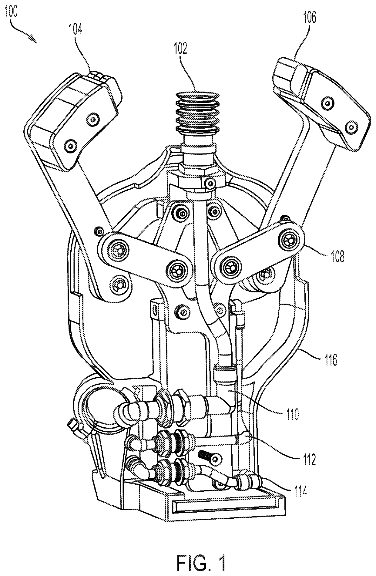
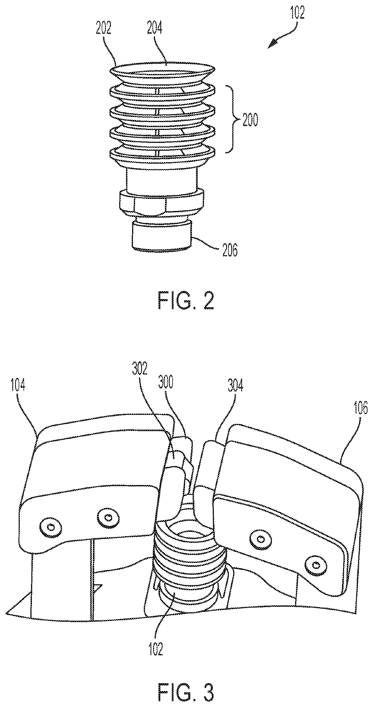
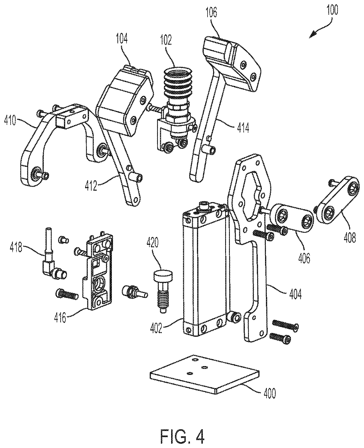
[0044]It should be understood that aspects of the present disclosure are described herein with reference to the figures, which show illustrative embodiments. The illustrative embodiments herein are not necessarily intended to show all embodiments in accordance with the present disclosure, but rather are used to describe a few illustrative embodiments. Thus, aspects of the present disclosure are not intended to be construed narrowly in view of the illustrative embodiments. In addition, although the present disclosure is described with respect to its application for pick-and-place applications, it is understood that the system could be implemented in any setting where a robotic gripper may be useful, such as in various stages in a supply chain, assembly line, manufacturing environment, storage and warehouse facility, sorting stations, laboratory, and retail and commercial settings.

[0045]FIG. 1 is a rear perspective view of a robotic gripper or apparatus according to an embodiment of t...


PUM


Abstract

The present disclosure generally relates to a robotic gripping system and method that utilizes vacuum suction and finger grasping, wherein the suction and grasping are actuated based on a dynamic collision model. In an exemplary embodiment, the present disclosure is directed to generating collision scenes of a surrounding environment which is used to determine possible collisions in a motion path, and which is used to selectively actuate the vacuum suction and / or finger grasping.

Description

CROSS-REFERENCE TO RELATED APPLICATION[0001]This application is related to, and claims benefit of and priority from Provisional Application No. 62 / 729,258 filed Sep. 10, 2018, the complete subject matter of which is hereby incorporated herein by reference in its entirety.BACKGROUNDField[0002]Embodiments of the present disclosure relate generally to the field of robotic gripping systems, and methods of control thereof, in order to manipulate objects for various purposes, such as, for example, picking, sorting, handling, packaging, and assembly.Description of Related Art[0003]Common robotic end effectors with gripping functionality are frequently highly complex, and highly customized to match the handled work piece. The end effectors may require various sensing mechanisms to assist the robotic system in locating, handling, and positioning objects of varying sizes, dimensions, colors, etc. However, current systems have in in handling irregularly-shaped objects, and current robotic syst...

Claims


Application Information

Patent Timeline
IPC IPC(8): B25J9/16B25J15/06B25J15/00B25J15/08B25J19/04
CPCB25J15/0028B25J9/1697B25J15/0616B25J15/08B25J9/1676B25J19/04B25J9/1612G05B2219/39558G05B2219/40497B25J13/081
Inventor JEONG, JUNWHITTINGTON, BRYANLIPAY, PETRHUMMEL, THOMAS JOHNHALLOCK, DAVID GABRIELMARTIN, ADRIANSEIZE, HUGOGEORGE, KEVINWOJCIECHOWSKI, SARAKEYES, NICHOLASRIZKALLA, ADAM
Owner OCADO INNOVATION
Learn More