Easy-to-mount actuator

Active Publication Date: 2020-03-12
SAFRAN ELECTRONICS & DEFENSE
View PDF0 Cites 0 Cited by
  • Summary
  • Abstract
  • Description
  • Claims
  • Application Information

AI Technical Summary

Benefits of technology

The patent describes an actuator that is designed to be easier to assemble and maintain. This is achieved by allowing a certain position between the inlet pinions, which results in a smaller angle and simplifies the transmission line arrangement. Overall, this design improves the efficiency and ease of use of the actuator.

Problems solved by technology

That solution is relatively complex, in particular because it is necessary for the shafts to be set angularly relative to one another in order to ensure that the actuator members acting on a common flight control surface are synchronized.
Unfortunately, the actuator system is so arranged that actuating the flight control surfaces between their extreme positions requires the shafts to turn through more than one revolution: a given angular position of a shaft can thus correspond to a plurality of positions of the flight control surfaces.
That greatly complicates initial assembly of the actuator system and also subsequent maintenance operations.
This results in relatively large weight for the actuator system as a whole.

Method used


Image

  • Easy-to-mount actuator
  • Easy-to-mount actuator
  • Easy-to-mount actuator

Examples


Embodiment Construction

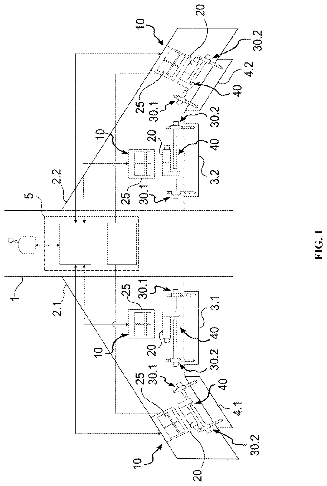
[0012]With reference to the figures, the invention is described herein in its application to an aircraft having a fuselage 1 and two wings 2.1, 2.2, each provided with an inner flap 3.1, 3.2 and an outer flap 4.1, 4.2. In known manner, the flaps 3.1, 3.2, 4.1, 4.2 are mounted on the wings 2.1, 2.2 to pivot between two extreme positions, and they are moved between those two positions by an actuator system controlled by a control unit 5 of the aircraft. The control unit 5 is a set of computers that are connected to the control instruments of the cockpit and to sensors distributed over the aircraft, and that control the engines and the flight control surfaces of the aircraft as a function of actions exerted by the pilot on the control instruments.

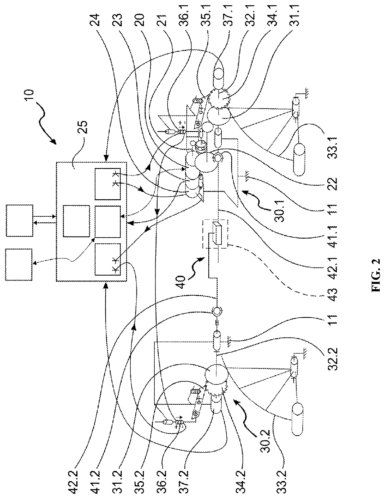
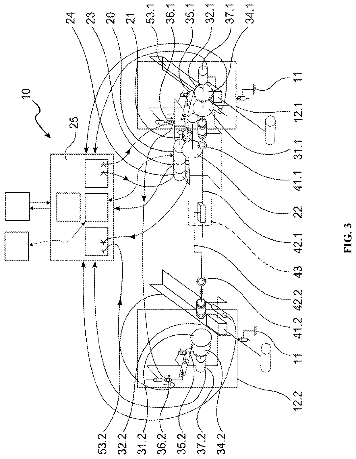
[0013]In this example, the actuator system comprises one actuator per flap 3.1, 3.2, 4.1, 4.2. Each actuator, given overall reference 10, comprises a structure 11 carrying a single motor 20 driving at least two members 30.1, 30.2 for actuating...


PUM


Abstract

An actuator for at least one flight control surface of an aircraft. The actuator has at least two actuator members for actuating the flight control surface between two extreme positions and a motor connected to the actuator members by at least one rotary motion transmission line. Each actuator member includes a drive pinion and the actuator is arranged so that the transmission line has an angular amplitude of less than one revolution during movement of the flight control surface between its two positions. The motion transmission line is arranged to allow only one angular position between the drive pinions and the actuator member.

Description

BACKGROUND OF THE INVENTIONField of the Invention[0001]The present invention relates to the field of aviation, and more particularly to actuating flight control surfaces of an aircraft such as ailerons, rudders, flaps, slats, elevators, . . . .Brief Description of the Related Art[0002]Flight control surfaces are hinged to the structure of the aircraft so as to be movable between two extreme positions, and they are moved between those two positions by actuator members having an inlet pinion connected to a transmission line connecting the actuator members to one another and to a common motor controlled by a control unit of the aircraft. The transmission line comprises shafts that are coupled to one another via fluted segments. That solution is relatively complex, in particular because it is necessary for the shafts to be set angularly relative to one another in order to ensure that the actuator members acting on a common flight control surface are synchronized. Unfortunately, the actu...

Claims


Application Information

Patent Timeline
IPC IPC(8): B64C13/50B64C13/34B64C9/02
CPCB64C9/02B64C13/34B64C13/50B64C13/38
Inventor MERCIER, GUILLAUMEMEHEZ, JÉRÔMEBEZIVIN, PHILIPPE
Owner SAFRAN ELECTRONICS & DEFENSE
Why Eureka
Try Eureka