Dual-springmagnetorheologicalabsorber
A magneto-rheological shock absorber and double spring technology, which is applied in the direction of spring/shock absorber, shock absorber, spring, etc., can solve the problems of poor vibration damping effect and unchangeable output force, and achieve a wide range of changes and easy Assembly and maintenance, economical processing and good results
- Summary
- Abstract
- Description
- Claims
- Application Information
AI Technical Summary
Problems solved by technology
Method used
Image
Examples
Embodiment 1
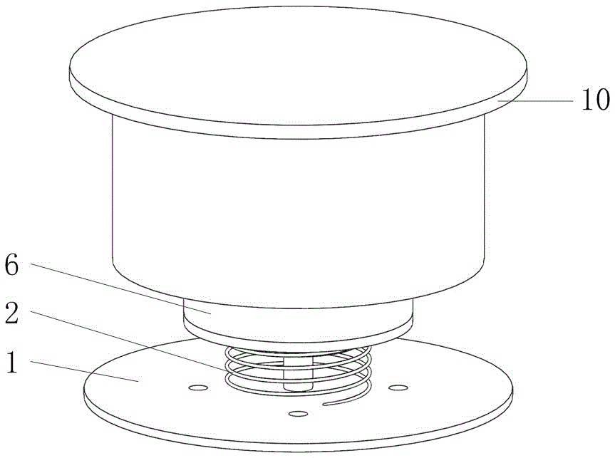
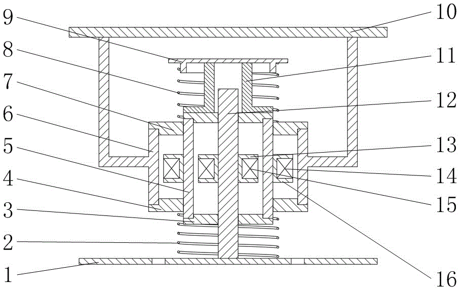
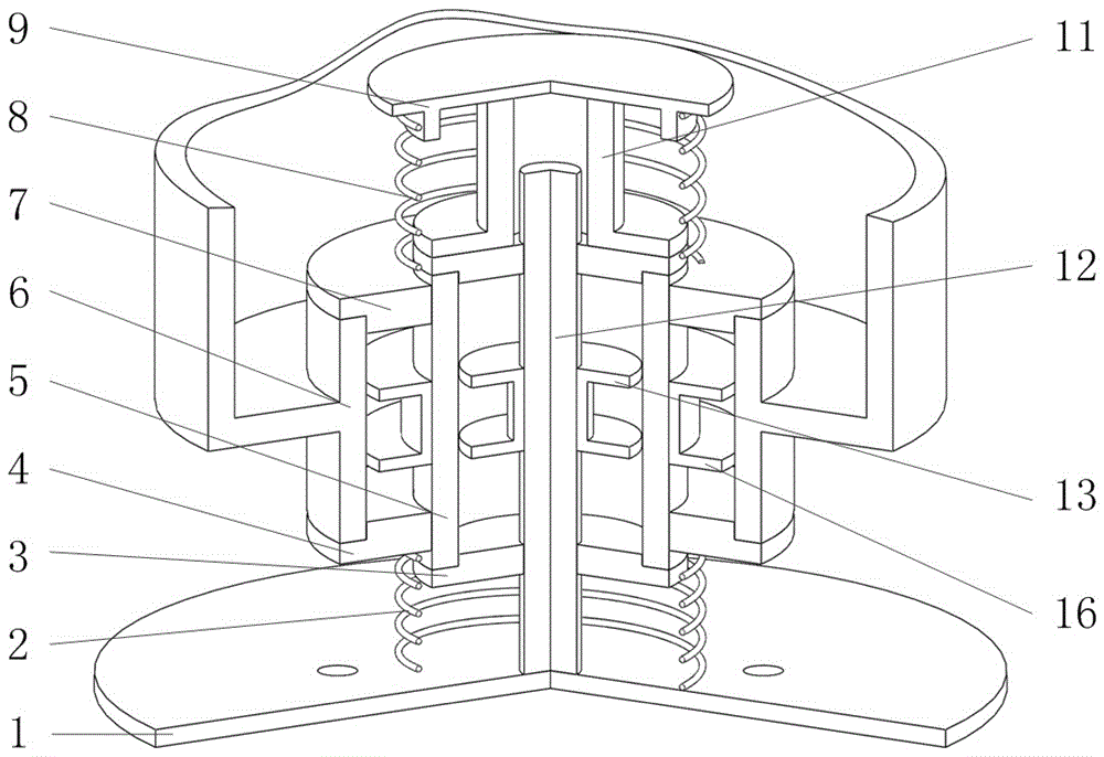
[0041] see figure 1 and figure 2 , the double-spring magneto-rheological shock absorber includes two springs with different rigidities, a closed inner cylinder 5 coaxially sleeved on the piston rod 12 and a closed outer cylinder 6, the inner cylinder 5 and the outer cylinder Magneto-rheological fluids are respectively arranged in 6 .
[0042] The two springs with different rigidities are a small rigidity spring 2 and a large rigidity spring 8, and the rigidity of the large rigidity spring 8 is twice that of the small rigidity spring 2.
[0043] see figure 2 , the piston rod 12 in the inner cylinder 5 is equipped with an inner excitation coil 15 through an inner splint 13 to form an inner piston; the inner cylinder 5 in the outer cylinder 6 is equipped with an outer excitation coil 14 through an outer splint 14 to form an outer piston. Both the inner excitation coil 15 and the outer excitation coil 14 are single-stage coils, and the materials of the inner splint 13 and th...
Embodiment 2
[0056] see Figure 7 , In this embodiment, the double-spring magneto-rheological shock absorber of Embodiment 1 has been rotated by 180°.
[0057] The piston rod connector 1 is installed on the vibration source foundation, the vibration source foundation is located above, and the object to be damped is suspended and placed. The double-spring magneto-rheological shock absorber of this embodiment can be applied to the establishment of a shock-absorbing platform that needs to be suspended for vibration reduction. Its working principle is similar to that of Embodiment 1, wherein both the small stiffness spring 2 and the high stiffness spring 8 are extension springs. This embodiment can also achieve the purpose of vibration reduction.
Embodiment 3
[0059] see Figure 8 One end of the extension tube 11 is connected to the axially extending end of the inner cylinder body 5 located outside the vibration-damping object placement part 10, and the other end of the extension tube 11 is a circular baffle plate 9. The high stiffness spring 8 is sleeved on the extension tube 11, one end of the high stiffness spring 8 is connected to the first sealing end cover 4 on the axial end surface of the outer cylinder body 6, and the other end of the high stiffness spring 8 is connected to the baffle plate 9. The piston rod connecting piece 1 and the small stiffness spring 2 on the piston rod 12 are correspondingly located in the damped object placement piece 10; one end of the small stiffness spring 2 is connected to the piston rod connecting piece 1, and the other end is connected to the shaft of the outer cylinder body 6 To the second sealing end cap 7 of the other end face. Small stiffness spring 2 and big stiffness spring 8 are tensio...
PUM
| Property | Measurement | Unit |
|---|---|---|
| Radial width | aaaaa | aaaaa |
Abstract
Description
Claims
Application Information
 - R&D
- Intellectual Property
- Life Sciences
- Materials
- Tech Scout
- Unparalleled Data Quality
- Higher Quality Content
- 60% Fewer Hallucinations
Browse by: Latest US Patents, China's latest patents, Technical Efficacy Thesaurus, Application Domain, Technology Topic, Popular Technical Reports.
© 2025 PatSnap. All rights reserved.Legal|Privacy policy|Modern Slavery Act Transparency Statement|Sitemap|About US| Contact US: help@patsnap.com


