Assembly tooling and assembly method for series magnetic pole boxes of large-scale motor rotor

A large-scale motor and assembly tooling technology, which is applied in electromechanical devices, manufacturing motor generators, manufacturing stator/rotor bodies, etc., can solve the problems of strong magnetic pole box repulsion, difficult assembly, large size of permanent magnets, etc., to prevent magnetization , High production efficiency, economical processing and good effect

Active Publication Date: 2020-08-28
青岛海西电气有限公司
View PDF5 Cites 0 Cited by
  • Summary
  • Abstract
  • Description
  • Claims
  • Application Information

AI Technical Summary

Problems solved by technology

For the assembly sequence of the pole box, the pole box can be assembled on the rotor first, and then the final assembly of the stator and rotor is carried out. The advantage of this assembly is that the pole box can be positioned on the rotor when it is assembled on the rotor, and the installation is convenient. The disadvantage is When the stator and rotor are assembled, the rotor has strong magnetism, which is very difficult for large motors
Another pole box assembly method is to first assemble the pole boxes into a string, then assemble the stator and rotor, and finally assemble the string of pole boxes to the rotor. However, due to the large size of the permanent magnet of a large motor, the magnetic pole The repulsion between the boxes is very strong, and the magnetic pole boxes must be operated with special tooling equipment when they are installed in series

Method used


Image

  • Assembly tooling and assembly method for series magnetic pole boxes of large-scale motor rotor
  • Assembly tooling and assembly method for series magnetic pole boxes of large-scale motor rotor
  • Assembly tooling and assembly method for series magnetic pole boxes of large-scale motor rotor

Examples


Embodiment Construction

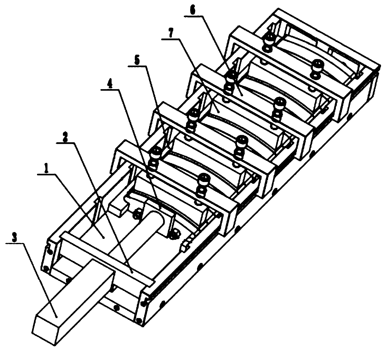
[0043] In order to better explain the present invention and facilitate understanding, the present invention will be described in detail below through specific embodiments in conjunction with the accompanying drawings.

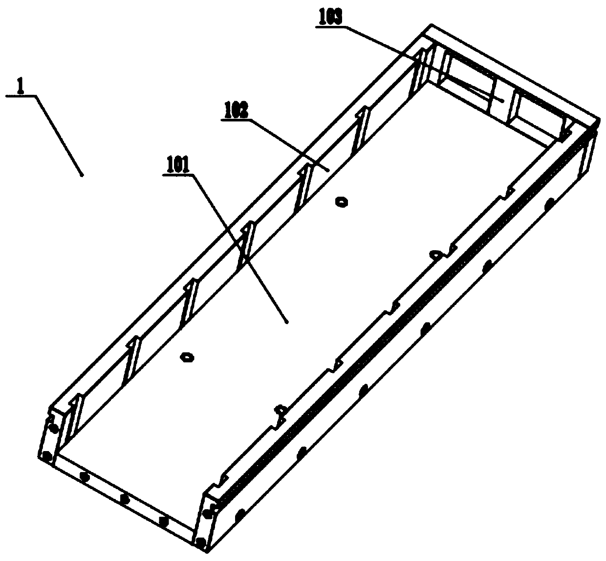
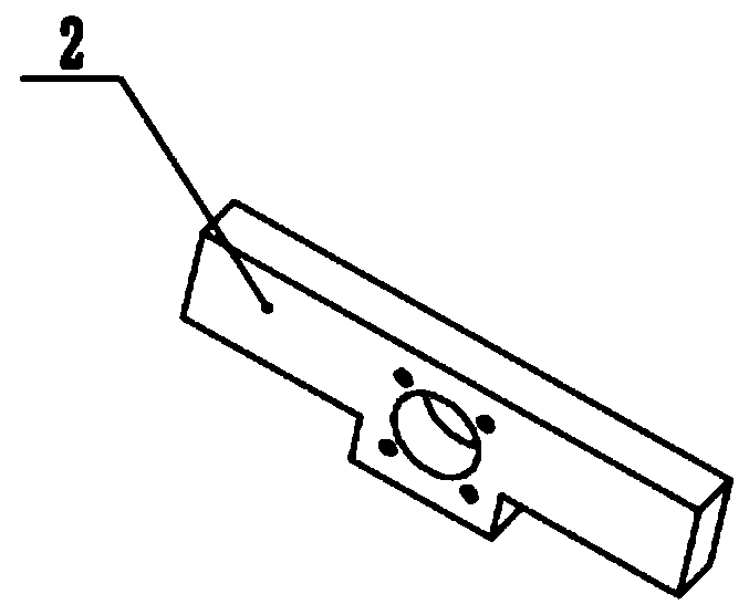
[0044] Such as Figure 1-Figure 6 As shown, the assembly tooling of the stringed magnetic pole boxes of the present embodiment includes a tooling base 1, an oil cylinder mounting plate 2, an oil cylinder 3, a push plate 4, a guide plate 5, a pressing tool 6, and a pressing plate 7, wherein the deoiling cylinder 3 In addition, the above structural materials are all made of non-magnetic materials. Specifically, the tool base 1, the oil cylinder mounting plate 2, the piston rod of the oil cylinder 3, the guide plate 5, the pressing tool 6 and the pressing plate 7 are all made of 316L stainless steel , The push plate 4 is made of brass, and all the fasteners in the present invention are also made of stainless steel. The material description in the present invention...


PUM


Abstract

The invention relates to the technical field of assembling process, in particular to a large-scale motor rotor string magnetic pole box assembling tool and assembling method. The assembling tool comprises a tool base, an oil cylinder mounting plate, a pushing plate, a pressing tool and a pressing plate. The tool base comprises a bottom plate, side plates and an end plate. The bottom plate, the side plates and the end plate are all detachably connected. The side plates are symmetrically installed on the left and right sides of the bottom plate and the end plate and are perpendicular to the endplate. The inner side of the side plates is provided with a plurality of longitudinal strip grooves. The spacing of the two adjacent longitudinal strip grooves is the same. The oil cylinder mounting plate can be inserted into the tool base along the symmetrically arranged longitudinal strip grooves. The outer side of the side plate sis provided with a transverse chute. The pressing tool can slidealong the symmetrically arranged transverse chutes. The structure is compact, the design of split bolt connection is applied to the tool base, the processing of parts is economical and good, and one or more of the bottom plate, the side plates or the end plate can be replaced to adapt to the assembling of the string magnetic pole box of various specifications.

Description

technical field [0001] The invention relates to the technical field of assembly technology, in particular to a large-scale motor rotor series magnetic pole box assembly tool and assembly method. Background technique [0002] According to the assembly position of permanent magnets, permanent magnet synchronous motors can be mainly divided into surface mount type and built-in type. In the surface-mounted permanent magnet synchronous motor, the permanent magnet is located on the outer surface of the rotor core. This kind of motor has a simple structure and is easy to install, but the anti-corrosion and anti-collision of the permanent magnet are difficult to deal with; while the permanent magnet of the built-in permanent magnet synchronous motor Located inside the rotor, there is a pole shoe made of ferromagnetic material between the outer surface of the permanent magnet and the inner circle of the stator core. The pole shoe protects the permanent magnet, making it anti-corrosio...

Claims


Application Information

Patent Timeline
Patent Type & Authority Patents(China)
IPC IPC(8): H02K15/03B23P21/00
CPCB23P21/00H02K15/03
Inventor 苏浩王雪郑海龙金晓宇阚立晨杜瑜鞠翔宇杨昊梁涵
Owner 青岛海西电气有限公司
Why Eureka
Try Eureka