Protective glass cutting machine

a cutting machine and glass tube technology, applied in glass severing devices, metal working devices, manufacturing tools, etc., can solve the problems of low cutting efficiency and slow separation speed of glass tubes, and achieve the effects of improving the stability of glass tube cutting, quick cutting, and increasing the separation speed of the cutting position

Inactive Publication Date: 2020-03-12
YAO JIANHUA
View PDF0 Cites 38 Cited by
  • Summary
  • Abstract
  • Description
  • Claims
  • Application Information

AI Technical Summary

Benefits of technology

[0013]The invention has the beneficial effects that the invention rotates along the glass tube by the heated cutting knife, and the glass tube is quickly cut, and the left and right sides of the cutting position of the glass tube are respectively provided with an output device and a conveying device to ensure the glass tube. The stability of the glass tube improves the stability of the cutting of

Problems solved by technology

Technical problem: in the conventional glass tube cutting device, the glass tube has poor stability, which causes the c

Method used


Image

  • Protective glass cutting machine
  • Protective glass cutting machine
  • Protective glass cutting machine

Examples


Embodiment Construction

[0023]The present invention will now be described in detail with reference to FIGS. 1 to 8.

[0024]For the convenience of description, the orientations described below are defined as follows: the up, down, left, and right front and rear directions described below are identical to the up, down, left, and right front and rear directions of the projection relationship of FIG. 1 itself.

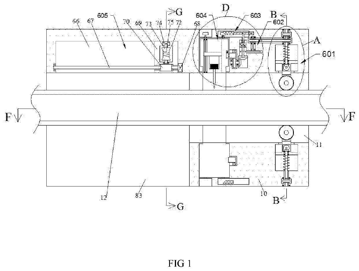
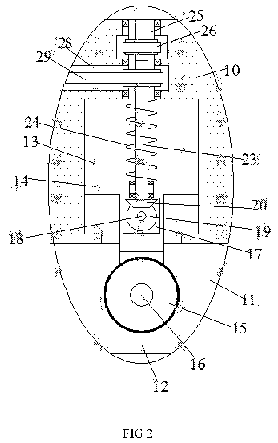
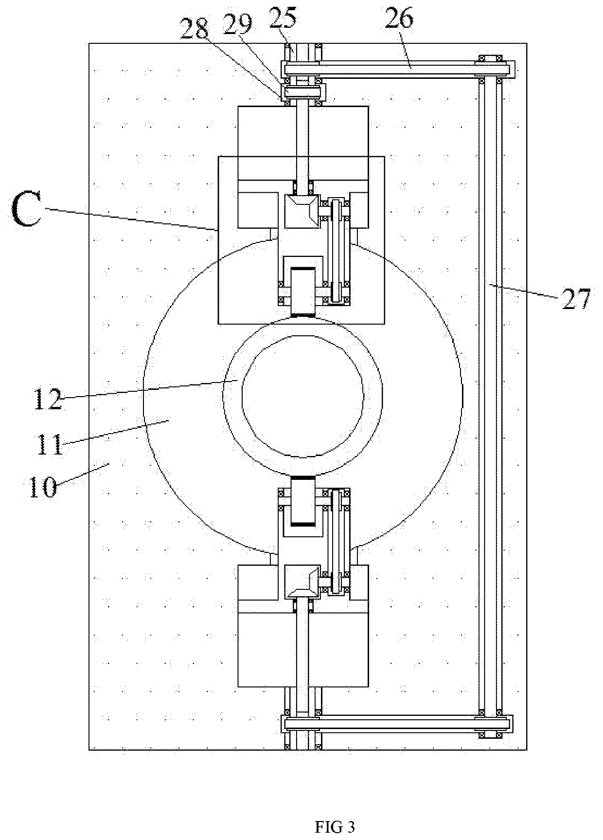
[0025]The invention relates to a protective glass cutting machine, which is mainly used for cutting work of a glass tube. The present invention will be further described below in conjunction with the drawings of the present invention: a protective glass cutting machine according to the present invention includes a cutting body 10, a cutting cavity 11 is disposed in the cutting body 10, and a conveying device 601 is disposed in the cutting cavity 11, and the conveying The device 601 includes a vertically symmetrical conveying wheel 15, and the conveying wheel 15 is oppositely rotated to drive the glass tube ...


PUM


Abstract

The invention discloses a protective glass cutting machine, including a cutting body, a cutting cavity is arranged in the cutting body, a conveying device is arranged in the cutting cavity, and the conveying device comprises a vertically symmetric conveying The rotating wheel, the opposite direction of the conveying wheel can drive the glass tube to move to the left for cutting. The invention rotates along the glass tube by the heated cutting knife, and the glass tube is quickly cut, and the glass tube is cut. The left and right sides are respectively provided with an output device and a conveying device to ensure the stability of the glass tube and improve the stability of the glass tube cutting. Secondly, when the glass tube is input to the left, the cutting knife and the glass tube are not abutted by the telescopic device.

Description

CROSS-REFERENCES TO RELATED APPLICATIONS[0001]The present application claims priority from Chinese application No. 2019107336694 filed on Aug. 9, 2019 which is hereby incorporated by reference in its entirety.TECHNICAL FIELD[0002]The invention relates to the technical field of glass cutting, in particular to a protective glass cutting machine.BACKGROUND OF THE INVENTION[0003]In the conventional glass tube cutting device, the position of the rotatable cutting knife is fixed, the rotation of the glass tube, the glass tube is cut under the action of the cutting knife, and the side of the glass tube is only input on the cutting process. If there is a fastening structure, the output side of the cutting position is easily deflected by the cutting force, which causes the cutting of the cutting to be uneven, and the cutting speed is low, and secondly, when cutting, due to the glass tube and the cutting When the cutter is kept in abutment state, the cutting blade is likely to scratch the sur...

Claims


Application Information

Patent Timeline
IPC IPC(8): C03B33/06C03B33/10B26D3/16B26D7/10
CPCC03B33/105B26D7/10C03B33/06B26D3/16
Inventor YAO, JIANHUA
Owner YAO JIANHUA
Why Eureka
Try Eureka