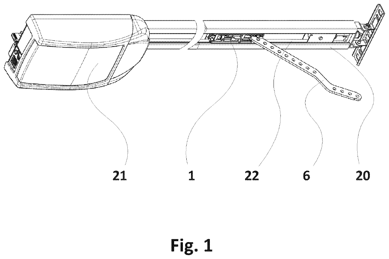
[0031]FIG. 1 shows an exemplary embodiment of the door drive according to the disclosure, which comprises a motor unit with a drive motor 21 which drives a power transmission device 22 configured as a toothed belt which moves along a rail 20 proceeding from the drive motor 21. In the rail 20 a drive carriage according to the disclosure is shiftably mounted, which is linearly movable by the linear movement of the toothed belt 22. The drive carriage includes a door driver 6 configured as a bent rod, which is articulated to a door (not shown) and produces a connection between drive carriage and door. Thus, the door can be opened and closed by means of the drive motor 21. For assembly, the drive carriage is pushed into the rail 20.
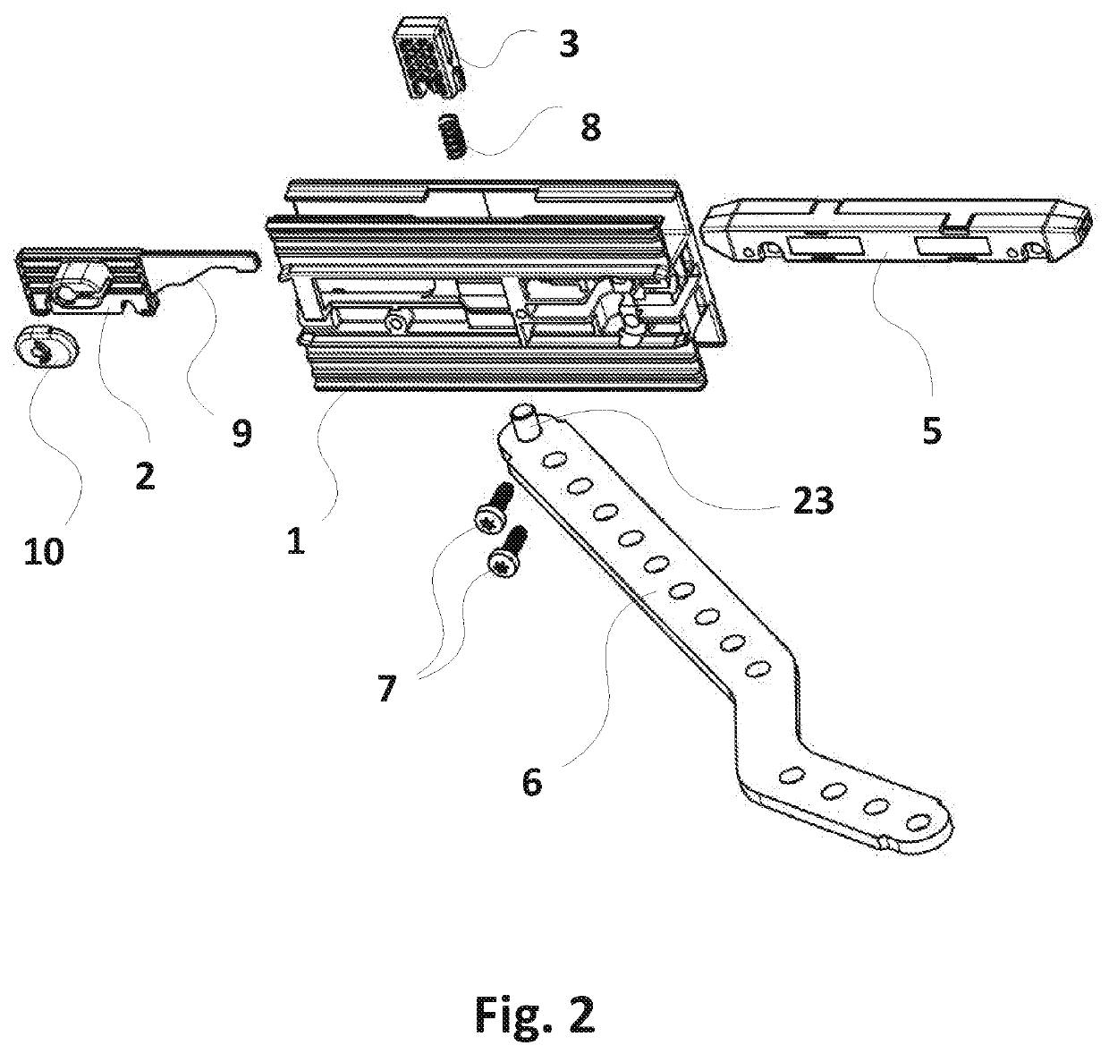
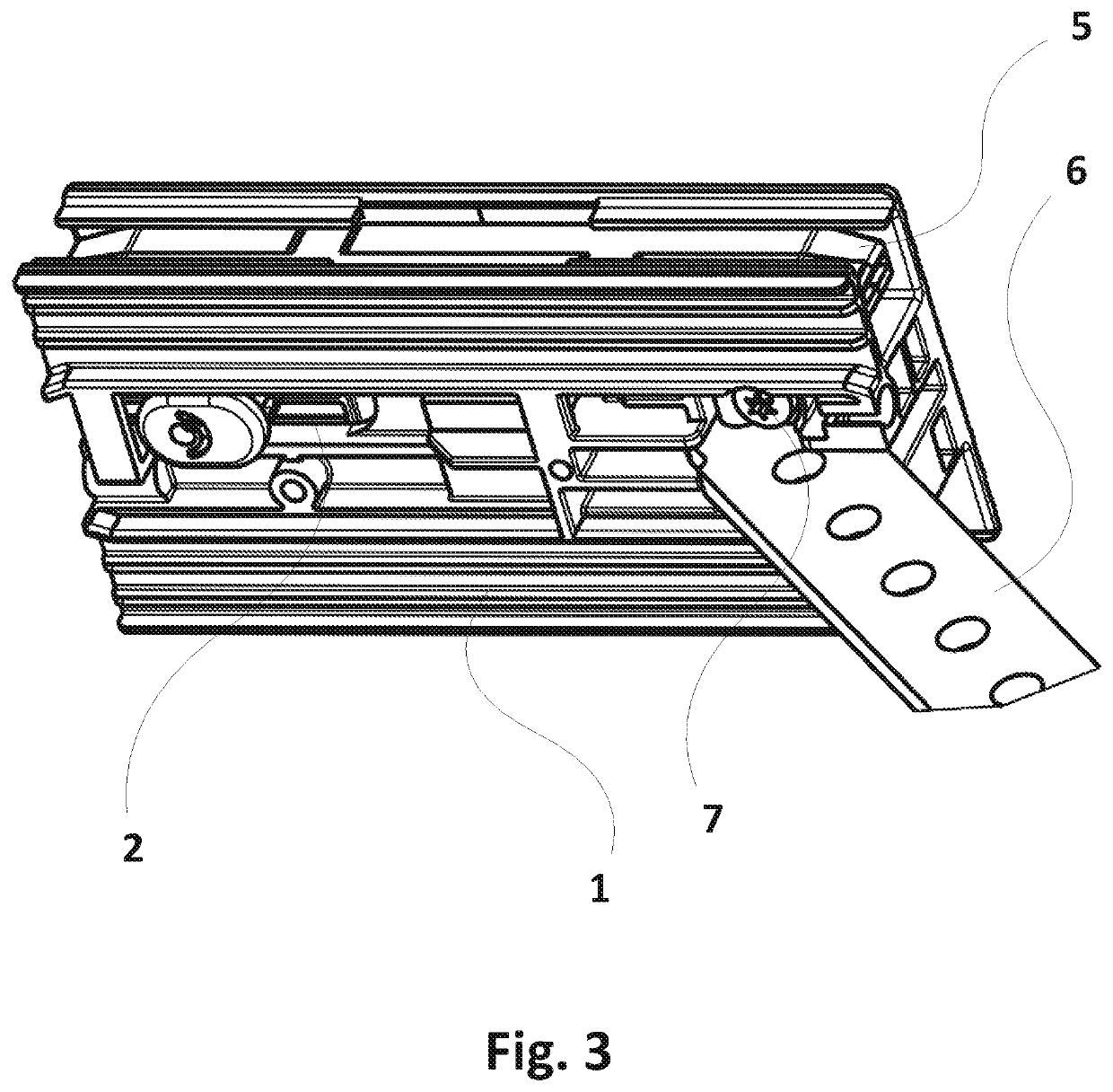
[0032]In the following, an exemplary embodiment of the drive carriage according to the disclosure will now be described with reference to FIGS. 2-4.
[0033]FIG. 2 shows a perspective exploded view of the drive carriage according to the disclosure, which comprises a one-part body 1, a carriage driver 5 connectable or connected with the toothed belt 22 of a door drive, a door driver 6 connectable with a door, a latch 3 and a latching slide 2. FIGS. 3 and 4 show the drive carriage in the assembled condition in a perspective view and in a cross-sectional top view of the underside of the body 1.
[0034]In the body 1 of the drive carriage the door driver 6 configured as a bent rod is mounted in a recess on the underside of the body 1 via a bolt element 23 with two screws 7. The recess is located centrally in the body 1 as seen perpendicularly to the direction of movement of the drive carriage or the carriage driver 5 so that the door driver 6 does not collide with the rail 20 of the door drive, which is open on its underside. The door to be moved is to be fastened to the door driver 6 so that the drive carriage is connected with the door.
[0035]The body 1 includes a recess 4 oriented along an axis aligned perpendicularly to the direction of movement of the drive carriage, into which a latch 3 comprising a flexible element 8 configured as a spring is inserted. The spring 8 urges the latch 3 away from the body 1 and out of the recess 4. The latch 3 is held by the latching slide 2 which includes a connecting link guide 9 aligned along the direction of movement of the drive carriage, which engages into a slot-shaped recess of the latch 3. At the end of the connecting link guide 9 a latching nose is disposed, which prevents a release of the connection between latching slide 2 and latch 3. The latching slide 2 hence is held at the latch 3 by means of the latching nose such that the latching slide 2 is fixed in this position and the latch 3 is fixed at the same time. This results in a very easy assembly of the coupling mechanism of latching slide 2 and latch 3, as the connecting link guide 9 must simply be pushed into the recess of the latch 3 until the latching slide 2 snaps into the latch 3. Subsequently, both parts are automatically coupled to each other and ready for use.
[0036]The body 1 includes a rail in which the oblong carriage driver 5 can move. The rail hence encloses the profile of the carriage driver 5 which in turn encloses and fixes the toothed belt 22 of the door drive. The recess 4, in which the latch 3 is disposed, opens laterally towards the rail.
[0037]By means of the connecting link guide 9 the latch 3 can take two positions: an unlocking position and a locking position. The same each correspond to a free-wheeling position and a drive position of the latching slide 2.
[0038]In the free-wheeling position of the latching slide 2 the same is maximally retracted into the body 1 and the latch 3 contacts the broader part of the connecting link guide 9. The latch 3 thereby is pressed into the recess 4 against the tension of the spring 8 to such an extent that the latch 3 does not protrude into the rail in which the carriage driver 5 can move. This is the unlocking position of the latch 3, in which the carriage driver 5 can freely move through the rail of the body 1 and in which carriage driver 5 and body 1 are not and cannot be coupled to each other. In this configuration the drive carriage thus is decoupled from the door drive and the door connected to the door driver 6 can be moved manually.
[0039]In the drive position of the latching slide 2 the same is maximally away from the latch 3 so that the latching nose abuts against the side of the latch 3 facing away from the latching slide 2, whereby a further pushing out of the latching slide 2 is prevented (see FIG. 4). Corresponding to the smaller width of the connecting link guide 9 in the region of the latching nose the latch 3 is not pressed into the recess 4 as far as in the locking position. The latch 3 is in the unlocking position, in which the same is pressed into the rail by the spring 8. When the carriage driver 5 now is moved through the rail of the body 1, there will be a contact with the part of the latch 3 protruding from the recess 4.
[0040]At its front and rear ends (as seen in the direction of its linear movement) the carriage driver 5 has bevels which are bevelled in the direction facing the latch 3. Due to a retraction of the carriage driver 5 into the rail, while the latch 3 is in the locking position, the latch 3 thereby is pressed into the recess 4 against the tension of the spring 8 so that the carriage driver 5 can move in the rail and is not blocked by the latch 3.
[0041]Furthermore, the carriage driver 5 has a recess 11 on the side facing the latch 3, which corresponds to the profile or cross-section of the latch 3 or is larger than the same so that the latch 3 completely fits into this recess 11. When the recess 11 of the carriage driver 5 now is located at the level of the latch 3, the same is pressed into the recess 11 of the carriage driver 5 by means of the spring 8, which carriage driver thereby is locked at the body 1. Now, there exists an in particular positive coupling between body 1 and carriage driver 5. Thereby, a mechanical connection between the toothed belt 22 inserted or fixed in the carriage driver 5 and the drive carriage and thus with the door articulated to the door driver 6 is produced.
[0042]FIGS. 3 and 4 show the mounted drive carriage with the latching slide 2 in the drive position. The carriage driver 5 is completely pushed into the rail of the body 1 and locked in this position by means of the latch 3 not visible here, which is in the locking position. In the body 1 the door driver 6 is fixed by the screws 7 by means of the bolt element 23 not visible in the sketch and is pivotally mounted about the longitudinal axis of the bolt element 23.
[0043]FIG. 4 illustrates the mode of action of the locking within the drive carriage. The latch 3 is located in the recess 4 and is pressed into the recess 11 of the carriage driver 5 by the spring 8. Furthermore, the mode of action of the latching slide 3 is illustrated here: In the drive position shown here, the same releases the latch 3 so that the same can be pressed into the recess 11 of the carriage driver 5 by means of the spring 8. When the latching slide 2 is pushed into the free-wheeling position against the spring force of the spring 8 of the latch 3, the locking is released and the body 1 can move independent of the carriage driver 5 and thus of the toothed belt 22 and the drive motor 21 connected thereto.
[0044]Latching slide 2 and latch 5 hence mutually hold or fix each other, and the latching slide 2 must be pushed from the drive position into the free-wheeling position against the spring force of the spring 8. Thus, it is prevented that the coupling between body 1 and carriage driver 5 is released inadvertently. The latching slide 2 furthermore includes a receiving device for receiving an actuating element by means of which the latching slide 2 can be moved over a certain distance from the free-wheeling position into the drive position and vice versa. This can be accomplished for example manually, but also automatically or by means of an actuator so that the motorized or manual operation of the door can easily be selected by the user. The actuating device for example can be a cable which includes a knot, a ball or a similar element which prevents slipping out of the receiving device. Furthermore, there is provided a securing device 10 in the form of a securing cap which serves the fixation of an actuating element which cannot be held by the receiving device alone, for example of a cable without knot or ball. The securing cap 10 includes an opening for the actuating element and after insertion of the actuating element is placed onto the receiving device of the latching slide 2.
[0045]As can be seen in FIG. 4, the region of the latch 3 contacting the connecting link guide 9 is bevelled in this exemplary embodiment in order to correspond with correspondingly bevelled regions of the connecting link guide 9 of the latching slide 2. This contacting region of the latch 3 is guided, in particular positively guided along the connecting link guide 9 when the latching slide 2 is brought from the free-wheeling position into the drive position and vice versa.
LIST OF REFERENCE NUMERALS
[0046] 1 body [0047] 2 latching slide [0048] 3 latch [0049] 4 recess for latch in the body [0050] 5 carriage driver [0051] 6 door driver [0052] 7 screws [0053] 8 flexible element [0054] 9 connecting link guide [0055] 10 securing device for actuating element [0056] 11 recess for latch in the carriage driver [0057] 20 rail (door drive) [0058] 21 drive motor (door drive) [0059] 22 power transmission device (door drive) [0060] 23 bolt element