
Direct cooling ice maker

Active Publication Date: 2020-03-12
ELECTROLUX HOME PROD CORP NV
View PDF7 Cites 8 Cited by
  • Summary
  • Abstract
  • Description
  • Claims
  • Application Information

AI Technical Summary

Benefits of technology

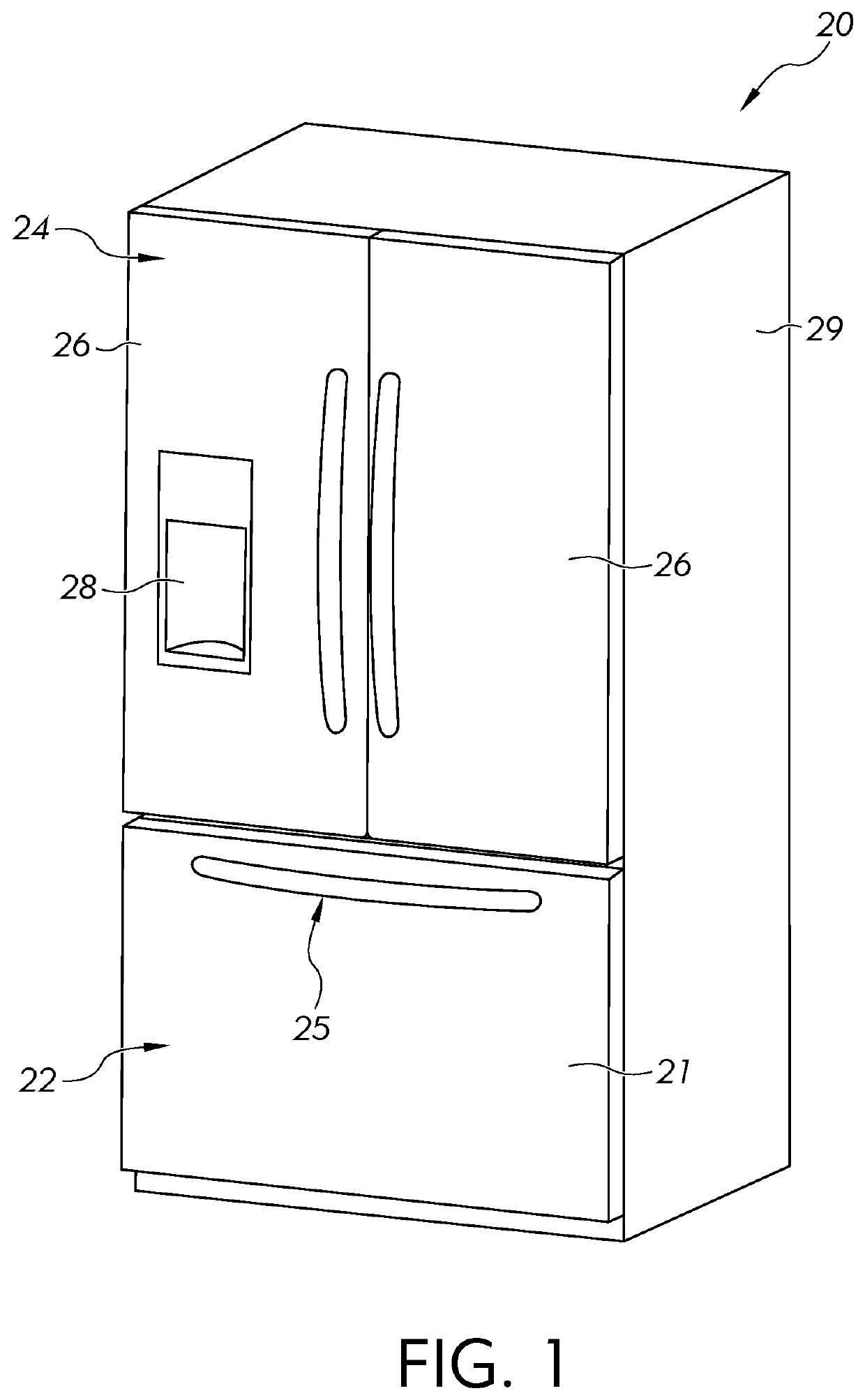
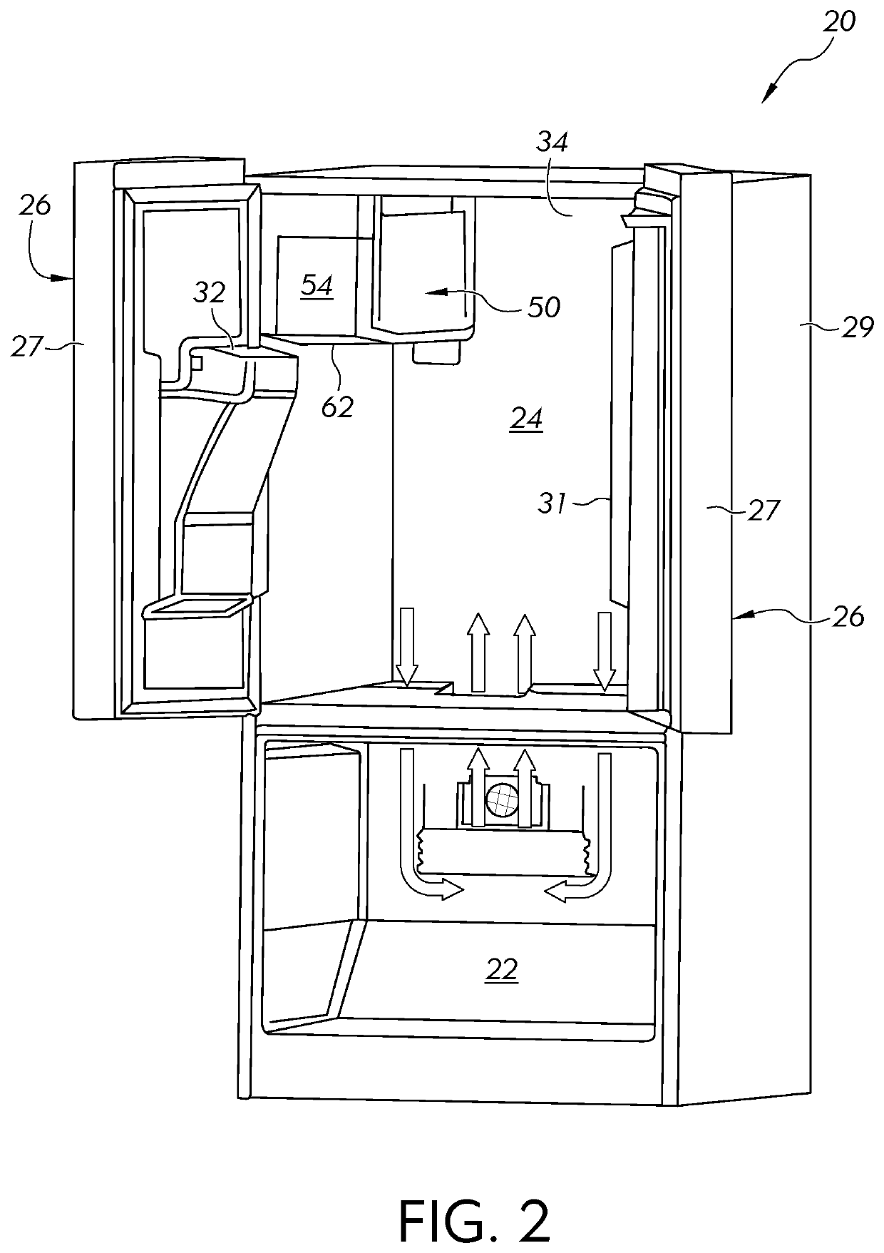
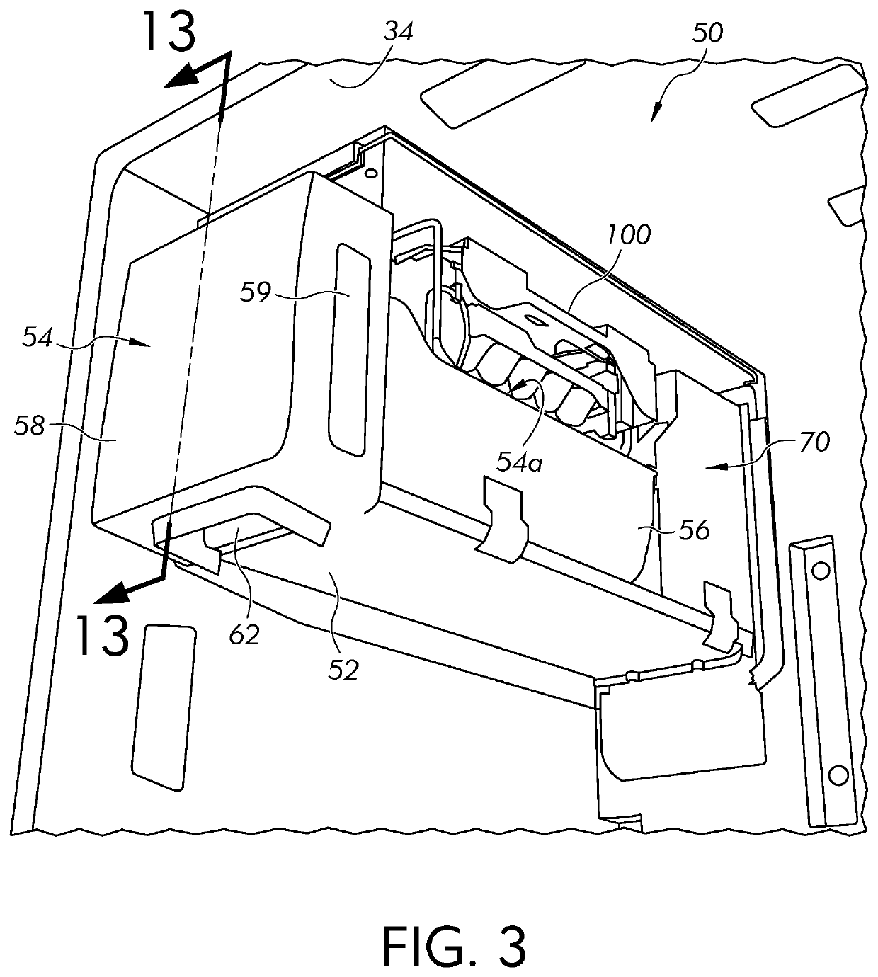
The patent describes a refrigeration appliance with an ice tray assembly for making ice pieces. The assembly includes an ice mold with cavities for the ice pieces, a heater for melting the ice mold, and an ice maker refrigerant tube for cooling the mold. The appliance also has a cover with a water fill cup and an outlet aligned with an inlet of the ice mold. This refrigeration appliance allows for efficient ice making and storage in a compact space.

Problems solved by technology

However, for refrigerators such as the so-called “bottom mount” refrigerator, which includes a freezer compartment disposed vertically beneath a fresh food compartment, placing the ice maker within the freezer compartment is impractical.
Thus, ice makers are commonly included in the fresh food compartment of bottom mount refrigerators, which creates many challenges in making and storing ice within a compartment that is typically maintained above the freezing temperature of water.

Method used


Image

  • Direct cooling ice maker
  • Direct cooling ice maker
  • Direct cooling ice maker

Examples


second embodiment

[0091]Referring to FIG. 9, a second embodiment ice tray assembly 200 similar to ice tray assembly 100 is shown. The second ice tray assembly 200 includes an ice mold 202. The second ice tray assembly 200 includes other components that are similar or identical to the ice tray assembly 100, but these components are not shown or described in detail below. For example, similar to the ice mold 102, the ice mold 202 includes a plurality of cavities (not shown) that are configured for receiving water to be frozen into ice pieces.

[0092]The ice mold 202 includes elongated internal cavities 202a that extend along at least one, and preferably opposite sides of the ice mold 202 in the lateral direction of the ice mold 202. The elongated cavities 202a are dimensioned and positioned to receive the first leg 152 and preferably also the second leg 154 of the ice maker evaporator 150. The ice mold 202 includes a rear surface 202b that is contoured to receive the connecting portion 156 of the ice mak...

fourth embodiment

[0113]FIGS. 15-23 illustrate an ice tray assembly 500. Referring to FIG. 15, the ice tray assembly 500, in general, includes an ice mold 510, an ice stripper 540, an ice ejector 550, a cover 570, a gear box 630 and a bail arm 610.

[0114]Referring to FIG. 16, the ice mold 510 is preferably made from a thermally conductive metal, like aluminum or steel. It is also preferred that the ice mold 510 is a single monolithic body. The ice mold 510 includes a top 512, a bottom 514 and lateral sides 516. A plurality of cavities 518 is formed in the top 512 of the ice mold 510. The plurality of cavities 518 is configured for receiving water to be frozen into ice pieces. The plurality of cavities 518 may be defined by weirs 522, and some or all of the weirs 522 have an aperture 524 therethrough to enable water to flow among the cavities 518. Referring to FIG. 20, the aperture 524 is contoured to extend to a location near a bottom of the cavities 518 for improving the free flow of water between ad...


PUM


Abstract

A refrigeration appliance includes a fresh food compartment for storing food items in a refrigerated environment having a target temperature above 0° C., a freezer compartment for storing food items in a sub-freezing environment having a target temperature below 0° C., a system evaporator for providing a cooling effect to at least one of the fresh food compartment and the freezer compartment, and an ice tray assembly disposed within the fresh food compartment for freezing water into ice pieces. The ice tray assembly includes an ice mold with an upper surface comprising a plurality of cavities formed therein for the ice pieces, a heater disposed on the ice mold and an ice maker refrigerant tube abutting at least one lateral side surface of the ice mold and cooling the ice mold to a temperature below 0° C. via thermal conduction and a cover having a water fill cup integrated into the cover and an outlet aligned with an inlet of the ice mold.

Description

CROSS-REFERENCE TO RELATED APPLICATIONS[0001]The present application is a continuation-in-part of U.S. application Ser. No. 15 / 852,022, filed on Dec. 22, 2017.FIELD OF THE INVENTION[0002]This application relates generally to an ice maker for a refrigeration appliance, and more particularly, to a refrigeration appliance including a direct cooling ice maker.BACKGROUND OF THE INVENTION[0003]Conventional refrigeration appliances, such as domestic refrigerators, typically have both a fresh food compartment and a freezer compartment or section. The fresh food compartment is where food items such as fruits, vegetables, and beverages are stored and the freezer compartment is where food items that are to be kept in a frozen condition are stored. The refrigerators are provided with a refrigeration system that maintains the fresh food compartment at temperatures above 0° C., such as between 0.25° C. and 4.5° C. and the freezer compartments at temperatures below 0° C., such as between 0° C. and...

Claims


Application Information

Patent Timeline
IPC IPC(8): F25C1/04F25D11/02F25C1/24F25C1/25F25C5/08F25C5/182F25C5/20
CPCF25C1/04F25C5/182F25D11/022F25C5/22F25C1/24F25C1/25F25C2700/06F25C2305/022F25C5/08F25B39/02F25C2305/024
Inventor SHI, ZHUOCHENMCCOLLOUGH, THOMAS W.
Owner ELECTROLUX HOME PROD CORP NV
Learn More