
Eureka
For R&D, Eureka makes reading and utilizing patents & technical documents easy.
Eureka AIR
Designed for self-driven R&D workflows. Generate viable solutions, solve complex R&D challenges, empower your innovation with AI.

Eureka Materials
Designed for material experts only. Revolutionize your material R&D, from search, analyze, to developing new materials.

TechResearch
Generate reliable direction feasibility study reports for your R&D in just a few steps.

TechSeek
Discover and master advanced knowledge NOW. Basics, ideas, possibilities, all at once.

TechMind
As an expert in R&D Theories, TechMind can generates customized viable solutions instantly.

TechRisk
Analyze your overall solution with one click, know your potential R&D risks in advance.

TechMonitor
Get weekly tech updates, stay abreast of the latest tech innovations and key insights.
Input detecting device
- Summary
- Abstract
- Description
- Claims
- Application Information
AI Technical Summary
Benefits of technology
Problems solved by technology
Method used
Image

Examples
first embodiment
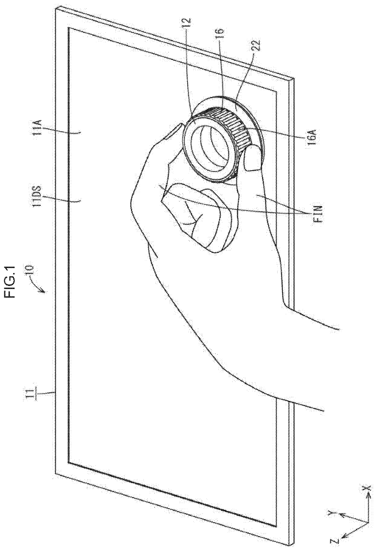
[0023]A first embodiment will be described with reference to FIGS. 1 to 9. In the embodiment section, an input detecting device 10 will be described. X-axis, Y-axis and Z-axis may be present in the drawings and each of the axial directions represents a direction represented in each drawing. A vertical direction is defined with reference to FIGS. 4, 6, and 7 and an upper side and a lower side in the drawings correspond to a front side and a back side, respectively.
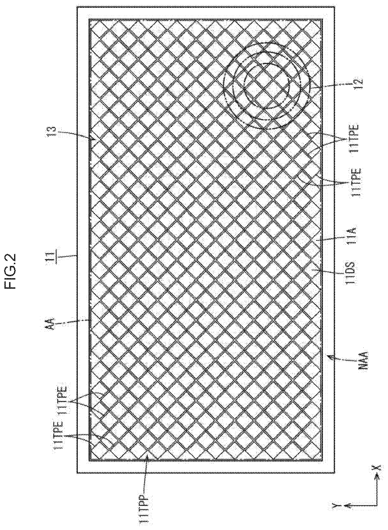
[0024]As illustrated in FIG. 1, the input detecting device 10 at least includes a liquid crystal display device (an input section) 11 that displays images through which a touch operation input (position input) is performed by a user, and a dial 12 that is mounted on the liquid crystal display device 11. The liquid crystal display device 11 has a touch panel function (position input function) of detecting a position (touch position) input by a user in addition to a display function of displaying images. In the present embodi...
second embodiment
[0049]A second embodiment will be described with reference to FIG. 10 or FIG. 11. In the second embodiment, a structure of an extended section 122 is altered. Configurations, operations, and effects similar to those of the first embodiment will not be described.
[0050]As illustrated in FIGS. 10 and 11, the extended section 122 according to the present embodiment is integrally included in a second rotary member 121. Accordingly, a first rotary member 120 that includes an operation surface 116A does not include the extended section 122. The second rotary member 121 includes a body section 121C and the extended section 122. The body section 121C is disposed on the back side with respect to the first rotary member 120 in the Z-axis direction and between the first rotary member 120 and a liquid crystal display device 111. The extended section 122 extends laterally from the body section 121C. Thus, the extended section 122 is integrally included in the second rotary member 121 that is disp...
third embodiment
[0052]A third embodiment will be described with reference to FIGS. 12 to 15. In the third embodiment, structures of a fixed member 215, a rotary member 216, and a rotation detection section 214 are altered from those of the first embodiment. Configurations, operations, and effects similar to those of the first embodiment will not be described.
[0053]As illustrated in FIGS. 12 and 13, the rotary member 216 according to the present embodiment include a first rotary member 220 and does not include the second rotary member 21 that is described in the first embodiment (refer FIG. 6). In such a configuration, as illustrated in FIGS. 13 and 14, the rotation detection section 214 is included as a separate component from the first rotary member 220 and is attached to the first rotary member 220. The rotation detection section 214 is formed by molding a metal plate with press molding. The rotation detection section 214 includes a base section 24 and a pair of pieces 251. The base section 24 is...
PUM
 Abstract
Description
Claims
Application Information
 - R&D Engineer
- R&D Manager
- IP Professional
- Industry Leading Data Capabilities
- Powerful AI technology
- Patent DNA Extraction
Browse by: Latest US Patents, China's latest patents, Technical Efficacy Thesaurus, Application Domain, Technology Topic, Popular Technical Reports.
© 2024 PatSnap. All rights reserved.Legal|Privacy policy|Modern Slavery Act Transparency Statement|Sitemap|About US| Contact US: help@patsnap.com