
Thermo Efficiency Measurement System

a measurement system and efficiency technology, applied in space heating and ventilation control systems, lighting and heating apparatuses, heating types, etc., can solve the problems of large size restriction of renewable energy sources, large energy consumption of environmental control, and long work hours of heating ventilation air conditioning equipment serving the space to maintain a set environment level in the spa

Inactive Publication Date: 2020-03-19
BUDDERFLY INC
View PDF0 Cites 2 Cited by
  • Summary
  • Abstract
  • Description
  • Claims
  • Application Information

AI Technical Summary

Benefits of technology

The patent describes a device that can measure the energy transfer rate (thermal efficiency) of a room and provide a standardized measurement. It also suggests using an external sensor to trigger testing when conditions are right, and running short tests when occupants are not in the space. The technical effects include improved energy efficiency, better monitoring of room performance, and reduced discomfort for occupants.

Problems solved by technology

However, it has been observed that renewable energy sources are typically restricted in size in the ability to generate megawatt hours when compared to fossil fuel burning plants.
Environmental control takes up a large portion of the overall energy consumption on the power grid.
For example, if a space has a very poor thermal envelop (i.e., allows energy to be easily transferred to or from the space), Heating Ventilation Air Conditioning (HVAC) equipment serving the space will have to work longer and harder to maintain a set environment level in the space.
Whether the construction materials were properly installed and whether they have been properly maintained can also impact the energy transfer rate.
While they may be able to point to the information previously described above, they are generally unable to provide concrete and granular data showing actual energy transfer rates for rooms or spaces within a company's facility.
Likewise, they are only able to discuss at a very general level overall expected savings for a facility.
Even in cases where products would intuitively improve for example, thermal efficiency, determining the return on investment of such improvements can be difficult without a reliable system to specifically measure these gains.
However, it is difficult to measure the efficiency and effectiveness of these changes.
Looking at the overall energy bill is not a reliable measurement technique as the overall bill reflects many variables and does not isolate the energy use to a given space to provide a good method of comparison.

Method used


Image

  • Thermo Efficiency Measurement System
  • Thermo Efficiency Measurement System
  • Thermo Efficiency Measurement System

Examples


Embodiment Construction

[0042]Referring now to the drawings, wherein like reference numerals designate corresponding structure throughout the views.

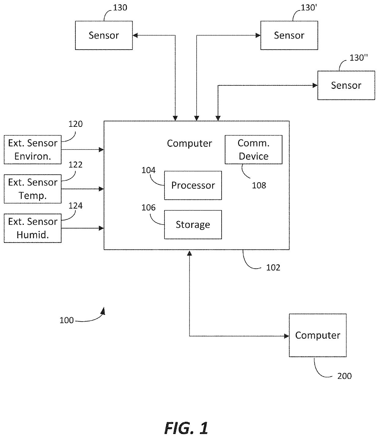
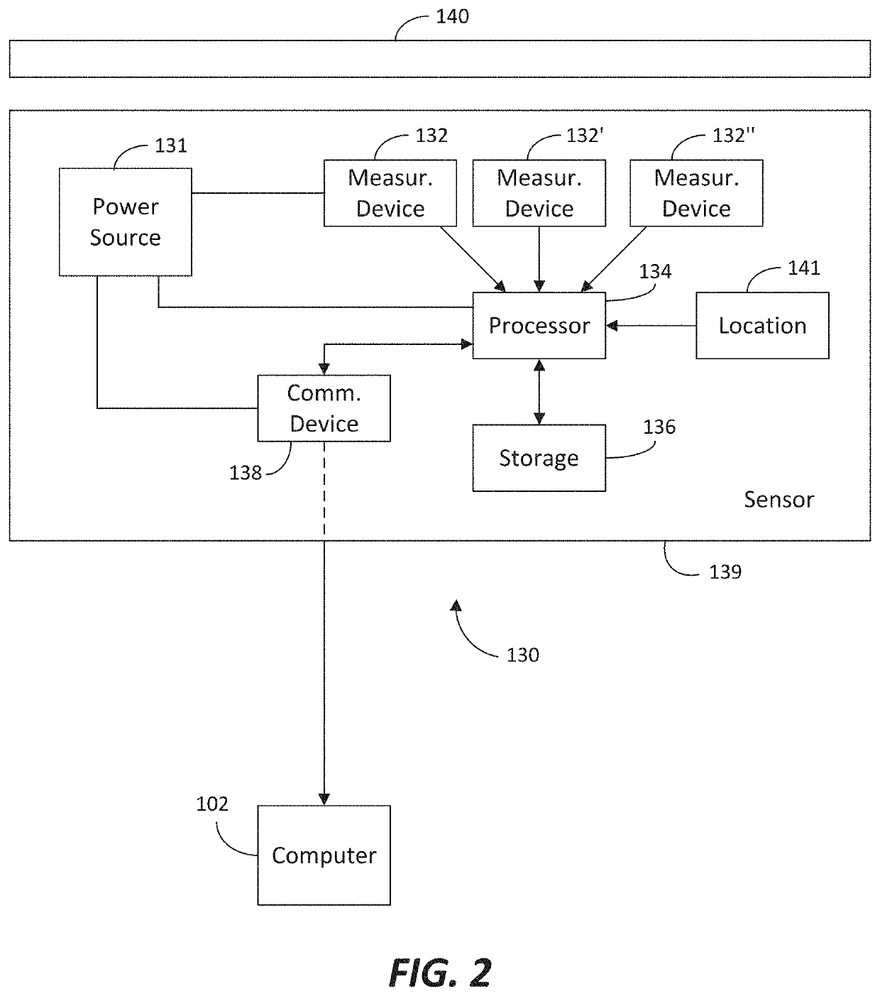
[0043]Turning to the drawings and specifically to FIGS. 1 and 2, FIG. 1 illustrates one configuration for the system 100 for determining an energy transfer rate of a room. The system includes a computer 102 that is coupled to a sensor 130. It is contemplated that multiple sensors 130, 130′, 130″ may be coupled to the computer 102. Also shown in FIG. 1, are external sensors including an environmental sensor 120, a temperature sensor 122 and a humidity sensor 124. It will be understood that these external sensors may be locally mounted sensors external to a facility containing the rooms to be measured, or these may be data feeds from a network connection from a local weather measurement station or the like. Additionally, the environmental sensor 120 may comprise a number of different sensors or data feeds providing information for wind speed and direction, solar ...


PUM


Abstract

Systems and methods are provided for determining an energy transfer rate of a room via one or more sensors to determine a baseline efficiency measurement of a room as well as delta efficiency gains obtained by making changes to internal or external factors affecting thermal efficiency. The system further include the automatic control for various equipment associated with the room and automatic measurement based on the status of the room.

Description

FIELD OF THE INVENTION[0001]The present invention relates to systems and methods for evaluating the thermal envelop of an individual space or room to determine the value of stepwise changes taken to improve the thermal envelop of the space. In particular, the system relates to a measurement device that can be freely placed in the space to gather specific environmental data that can be compared / combined with target or expected data or with alternative measurement data to achieve an energy reduction goal.BACKGROUND OF THE INVENTION[0002]Energy use has been a concern for companies for many years leading to many different efforts to quantify energy use with the purpose of determining how energy use could be reduced. For years it has been the escalating costs associated with excessive energy use that has driven the desire to lower energy usage. As energy costs continue to escalate, cost is still a driving factor motivating companies to look for new and better ways to reduced energy usage...

Claims


Application Information

Patent Timeline
Patent Type & Authority Applications(United States)
IPC IPC(8): F24F11/46F24F11/63
CPCF24F2110/20F24F11/63F24F2110/32F24F11/46F24F2110/10F24F2110/12F24F2130/20F24F2120/10
Inventor SUBBLOIE, ALBERTBUDA, KENNETHLEEMET, JAANVEIKOS, MARK ALPHONSE
Owner BUDDERFLY INC
Learn More