Supercharge Your Innovation With Domain-Expert AI Agents!

Feed systems and methods for rotary screen separators

a technology of rotary separator and feed system, which is applied in the direction of filtration separation, separation process, moving filter element filter, etc., can solve the problems of fine opening, inability to pass as much liquid material through the perforation, and undetectable high volume of solids

Inactive Publication Date: 2020-03-26
DARITECH
View PDF0 Cites 1 Cited by
  • Summary
  • Abstract
  • Description
  • Claims
  • Application Information

AI Technical Summary

Benefits of technology

This configuration enhances the separation efficiency, allowing for higher processing rates and improved separation of solids and liquids, with the ability to maintain separate filtrate streams for further processing.

Problems solved by technology

However, a screen with fine openings also does not allow as much liquid material through the perforations as does a coarse screen.
Conversely, a coarse screen allows an increased volume of liquid material to flow through the perforations, but a separator having a coarse screen may allow an undesirably high volume of the solids to escape with the increased volume of liquid material.

Method used


Image

  • Feed systems and methods for rotary screen separators
  • Feed systems and methods for rotary screen separators
  • Feed systems and methods for rotary screen separators

Examples


Embodiment Construction

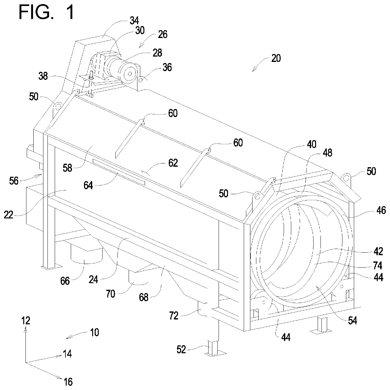
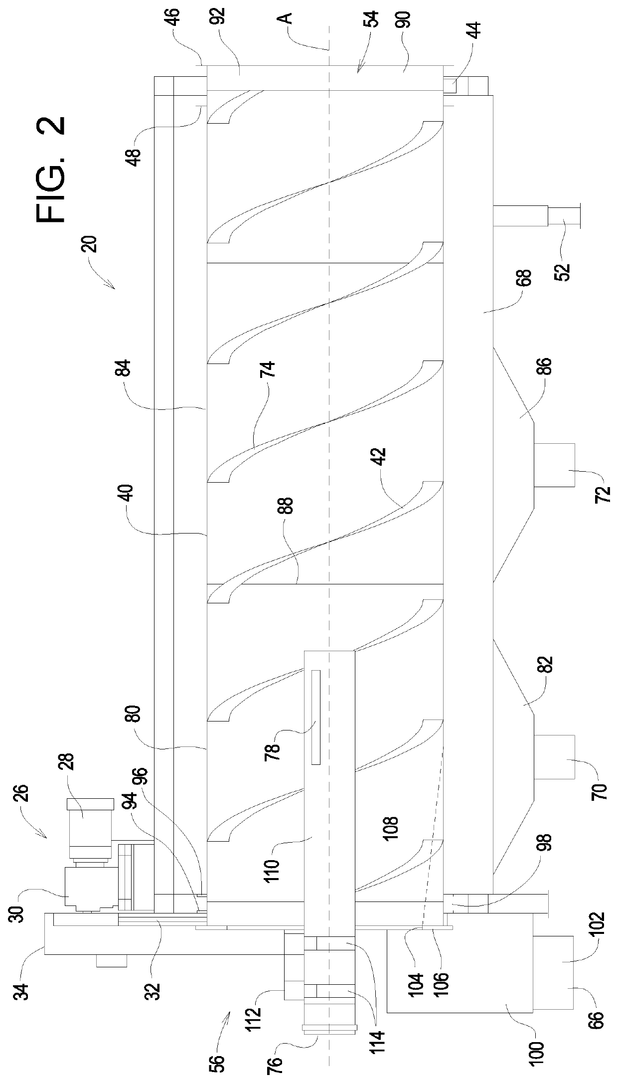
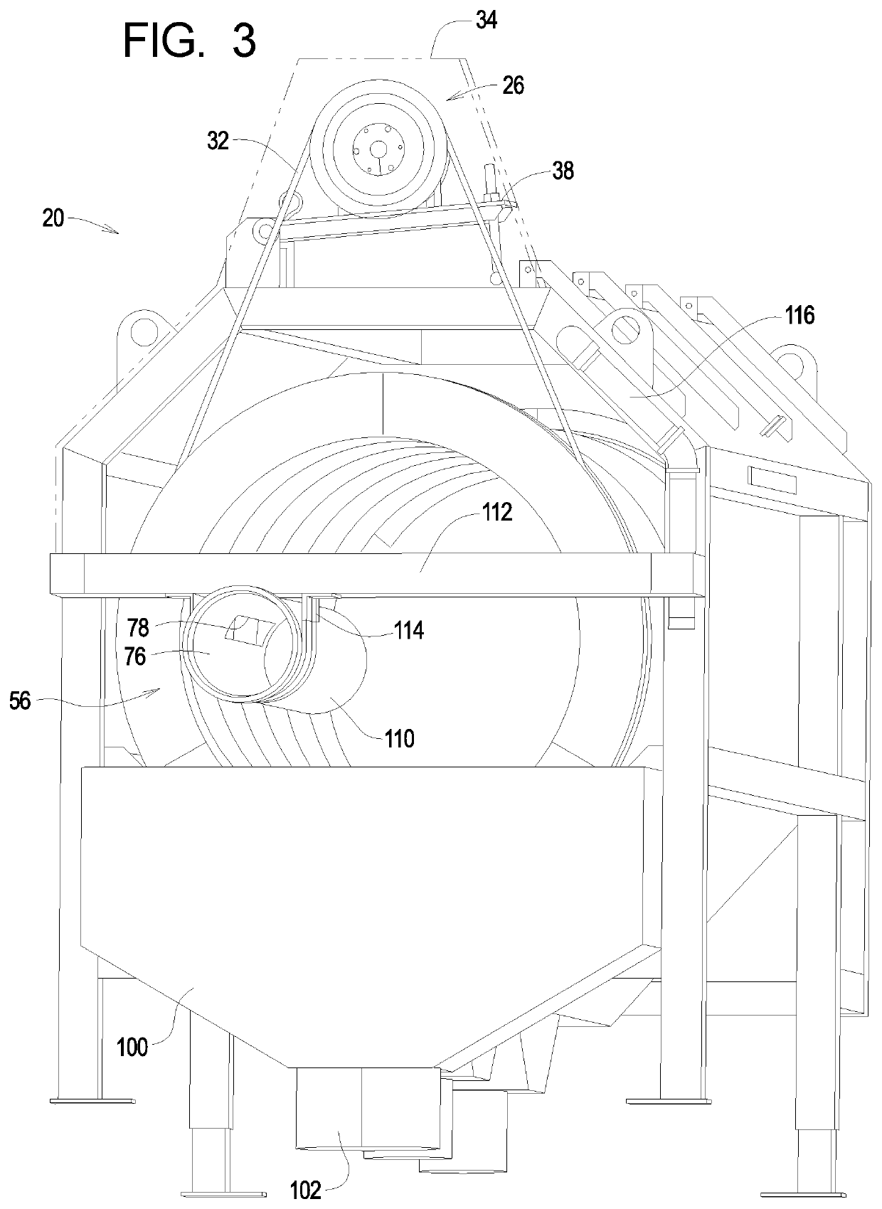
[0029]A rotary screen separator is disclosed herein which may generally comprise a frame and a rotating perforated screen supported by the frame. In one form, the rotating screen is horizontally aligned at a slight angle and often comprises an internal screw flight. The screw flight is operatively configured to reposition the media to be separated from the input end of the separator to the solids discharge end. As the material moves through the screen separator, liquid and fine particles are removed through the perforations in the screen.

[0030]The example hybrid rotary screen separator of the present invention comprises at least two separate regions each comprising a different screen size. In the example hybrid rotary screen separator disclosed herein, the perforations of the screen on the input end of the separator comprise a much finer hole size than the perforations toward the solid discharge end. These regions of fine screen and coarse screen may be separate structures which may...


PUM

PropertyMeasurementUnit
diameteraaaaaaaaaa
diameteraaaaaaaaaa
angleaaaaaaaaaa

Abstract

A rotary screen separator includes a screen having a substantially cylindrical shape extending from a feed end to a discharge end along a horizontal longitudinal axis. The screen is perforated in a plurality of discrete regions. The regions including at least a first perforation region wherein the screen is perforated in a first perforation pattern and a second perforation wherein the screen is perforated in a second perforation pattern. The first perforation pattern is sized to allow liquid and finer particulate matter to pass through the perforations and the second perforation pattern is sized to allow liquid and coarser particulate matter to pass through the perforations in the second perforation pattern. A first vane structure is helically shaped at a first vane depth having a first vane pitch and handedness selected to advance feedstock within the screen as the screen is rotated in operation.

Description

PRIORITY CLAIM[0001]The instant application is a continuing application claiming priority to U.S. patent application Ser. No. 16 / 372,198, filed on 1 Apr. 2019, which, itself, is a continuing application claiming priority to U.S. patent application Ser. No. 14 / 722,590 filed 27 May 2015 and issued as U.S. Pat. No. 10,286,340 issued to DeWaard on May 14, 2019, which, itself, claims benefit of U.S. Provisional Application Ser. No. 62 / 003,490 filed 27 May 2014, now expired, the contents of which are incorporated herein by reference.FIELD OF THE INVENTION[0002]This disclosure relates to the field of rotary separators and, more particularly, to feed systems for rotary separators that are used to separate effluent into different fractions depending upon the volume of the solid components.BACKGROUND OF THE INVENTION[0003]Rotary screen separators are often used to process effluent such as waste from a dairy operation. Generally speaking, rotary screen separators separate a feed material into ...

Claims


Application Information

Patent Timeline
Patent Type & Authority Applications(United States)
IPC IPC(8): B01D33/11B01D33/80B01D33/067B01D33/72B01D33/50
CPCB01D33/50B01D33/801B01D33/067B01D33/11B01D33/72C02F11/126
Inventor DEWAARD, DAVID
Owner DARITECH
Features
  • R&D
  • Intellectual Property
  • Life Sciences
  • Materials
  • Tech Scout
  • Unparalleled Data Quality
  • Higher Quality Content
  • 60% Fewer Hallucinations
Learn More