Sea Tunnel

a tunnel and sea tunnel technology, applied in the field of sea tunnels, can solve the problems of difficult to ensure the safety and stability of the structure of such bridges, relatively large risks, poor stability and safety, etc., and achieve the effects of less influenced by diastrophism, stable and firm structure of the whole body, and high stability

Active Publication Date: 2020-03-26
TONGHUA NORMAL UNIV
View PDF13 Cites 2 Cited by
  • Summary
  • Abstract
  • Description
  • Claims
  • Application Information

AI Technical Summary

Benefits of technology

The sea tunnel has a hollow cavity that is divided into two layers: the first layer is above sea level and allows for easy passage, while the second layer is immersed in seawater. The second layer has water holes that allow seawater to enter and become part of the tunnel. The sea tunnel is designed to resist the buoyancy and impact force of seawater, ensuring its stability and firmness. Compared to traditional undersea tunnels, the sea tunnel is less influenced by seawater pressure, tsunamis, and other oceanic factors, making it safer and less expensive.

Problems solved by technology

However, the applicant finds at least the following technical problems in the prior art:
the sea-crossing bridge is very difficult to build generally by deeply striking reinforcing bars into the seabed, then cementing to form bridge piers, finally building a bridge body located on the sea level; the sea has a changeable and severe environment, so it is very difficult to ensure safety and stability of the structure of such bridge between two coasts having a large span; and
the undersea tunnel does not prevent ship from sailing on the sea and is not influenced by weather conditions such as strong wind and heavy fog; however, the undersea tunnel is completely built on the seabed, is greatly influenced by diastrophism, seawater pressure, tsunami and the like and has relatively large risks and poor stability and safety; and the existing undersea tunnel is generally built in a neritic region so as to bear a small seawater pressure, but in an abyssal region, the undersea tunnel cannot be built due to influence of seawater pressure, diastrophism and the like.
Additionally, the existing undersea tunnel has high costs and is inconvenient to maintain.

Method used


Image

  • Sea Tunnel
  • Sea Tunnel
  • Sea Tunnel

Examples


embodiment

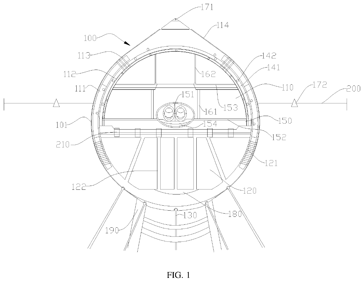
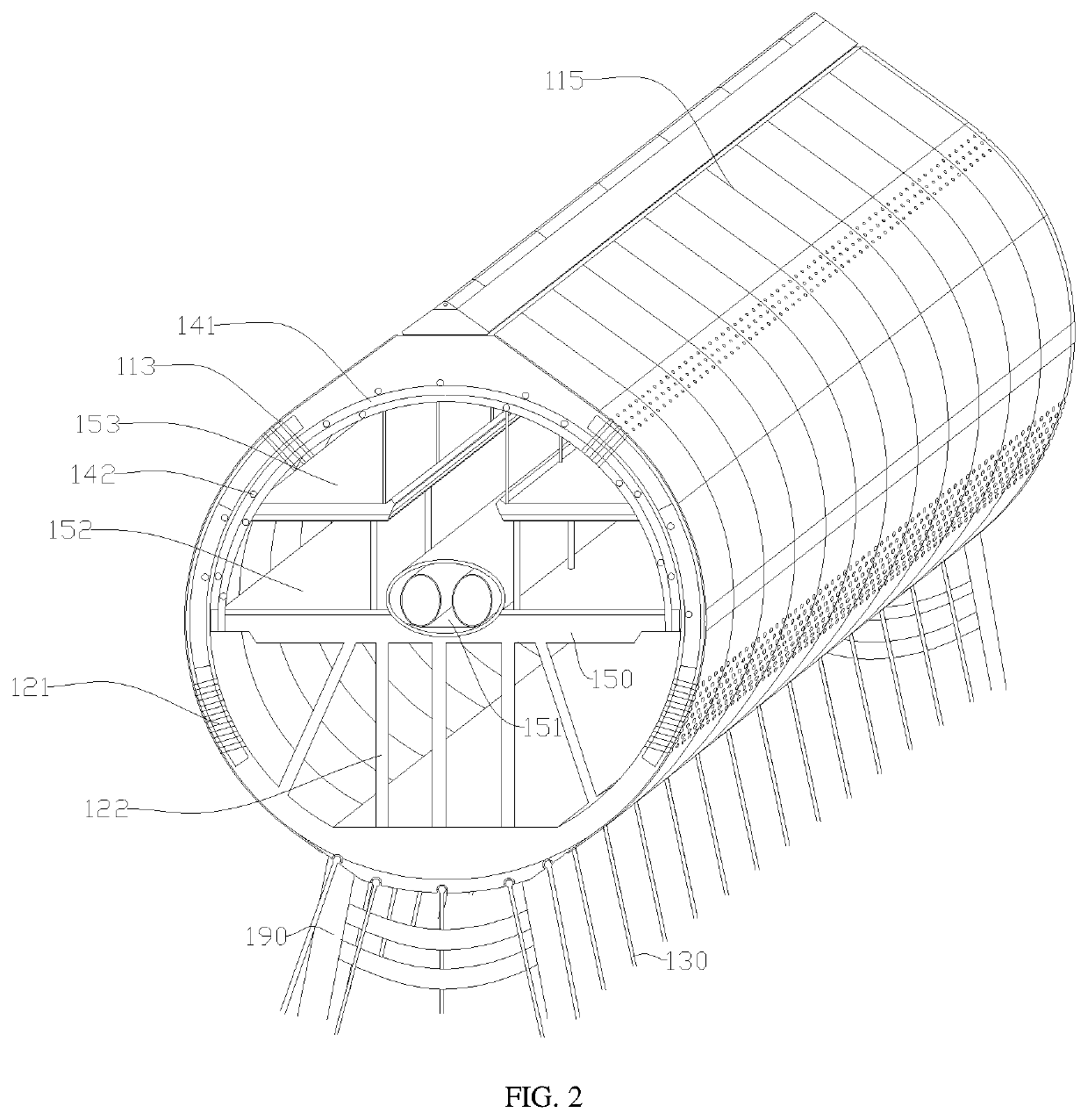
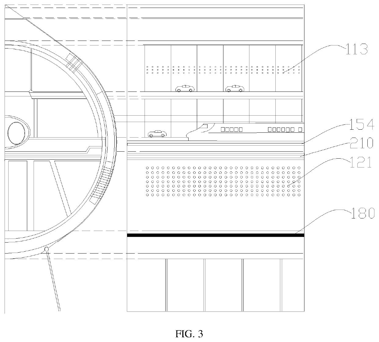
[0034]As shown in FIG. 1, FIG. 2 and FIG. 3, the embodiment provides a sea tunnel 100 which is mainly built between two coasts.

[0035]The sea tunnel 100 comprises a body 101. The body 101 has a hollow cavity extending from one end to the other end. The shape of the body 101 is not limited and may be a rectangle, an irregular polygon and the like. Preferably, the body 101 is cylindrical to facilitate production and process and to reduce and resist the impact force of the seawater in the embodiment.

[0036]The cavity is divided into mutually independent first cavity 110 and second cavity 120 by a passage pavement 150. In the embodiment, the first cavity 110 is mainly used for allowing passage. The first cavity 110 is wholly or partly protruded out of the sea surface. The second cavity 120 is immersed in the seawater. It should be noted that a part of the body 101 is protruded out of the sea level (namely the first cavity 110) while the other part of the body 101 is immersed under the sea...


PUM


Abstract

The present disclosure provides a sea tunnel, and relates to the technical field of sea-crossing bridge tunnels. The sea tunnel comprises a body; and the body has a hollow cavity extending from one end to the other end, the cavity is divided into mutually independent first cavity and second cavity by a passage pavement, the first cavity is mainly used for passing and is wholly or partly protruded out of the sea level, the second cavity is immersed in the seawater, water holes are formed in the second cavity, and the second cavity is communicated with the seawater through the water holes. When the seawater impacts one side of the body, the second cavity is immersed in the seawater, and the seawater flows into the second cavity, so the body is not easy to be flushed over by the seawater.

Description

CROSS REFERENCE TO RELATED APPLICATION[0001]This application claims the benefit of and takes priority from Chinese Patent Application Serial No. 201811103779.4 filed on Sep. 20, 2018 the contents of which are herein incorporated by reference.TECHNICAL FIELD[0002]The present disclosure relates to the technical field of sea-crossing bridge tunnels, and specifically relates to a sea tunnel.BACKGROUND OF THE INVENTION[0003]Development of economy facilitates growth of traffic demand and accelerates development of sea-crossing engineering. Currently, a transportation building between two coasts having a large span mainly comprises a sea-crossing bridge and an undersea tunnel.[0004]However, the applicant finds at least the following technical problems in the prior art:[0005]the sea-crossing bridge is very difficult to build generally by deeply striking reinforcing bars into the seabed, then cementing to form bridge piers, finally building a bridge body located on the sea level; the sea has...

Claims


Application Information

Patent Timeline
IPC IPC(8): E02D29/067E01B25/00
CPCE01B25/00E02D29/067E01C1/002E02D29/063
Inventor DU, DI
Owner TONGHUA NORMAL UNIV
Why Eureka
Try Eureka